AH-New
condensing air handling unit
APEN GROUP SPA reserves the right to make changes deemed to be required to its products or documentation
52
code HG0310.05GB ed.A-2010
AH
53
code HG0310.05GB ed.A-2010
AH
HG0131.00 A
003
HG0131.00 A
003_A
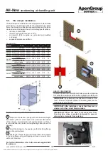
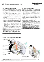
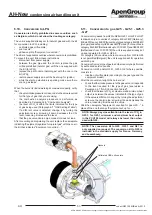
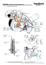
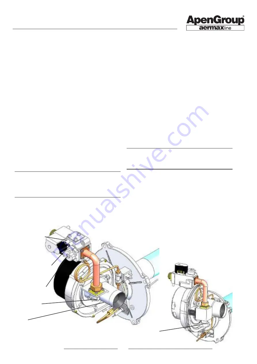
Venturi
Gas intake pressure
connector (IN)
OFFSET adjustment screw
OFFSET pressure intake
(Pascal)
CO
2
adjustment
For models: PCH020, PCH034, PCH045, PCH065, PCH080
For models: PCH105
CO
2
adjustment
6.8.
S
tarting up for the first time
The PCH heater module is supplied already set up and tested
for the gas specified on the nameplate. Before turning on the
PCH module check the following:
•
make sure the gas being supplied matches the gas for which
the PCH has been set up;
•
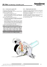
check, with the pressure intake "IN" on the gas valve, that
the valve input pressure corresponds to that required for
the type of gas being used;
•
check that electrical connections correspond to those
indicated in this manual or other wiring diagrams enclosed
with the unit;
•
check that efficient earthing connections have been
completed, carried out as specified by current safety
regulations;
•
power on the heater with the general switch located on the
unit and insert the power plug inside the PCH compartment.
To turn on the heater, follow the instructions below:
•
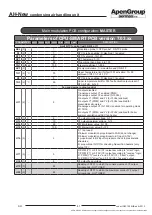
Check that the display shows RDY; if OFF is displayed
instead, work on the control, under FUN, and set the
device to ON;
•
Check that the Tin value is higher than the Von value on
the LCD display.
When ON appears on the LCD display, the heater starts the
ignition cycle.
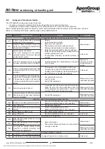
NOTE: Frequently, when turned on for the first time,
the pilot burner cannot ignite because there is air in
the gas pipe. This will lock out the equipment. You will
need to reset the equipment and repeat the operation
until it ignites.
6.9.
Analysis of combustion
Wait until the heater is switched on. Check that the heater is
running at maximum power by using one of the two methods
below:
•
check that Tin input signal is equal to 10 V;
•
from the LCD display, access the REG menu, then use
the Hi and Lo controls to force operation at maximum or
minimum output.
At maximum output, check again that the input pressure in the
valve corresponds to the value required; adjust if necessary.
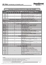
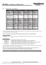
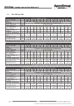
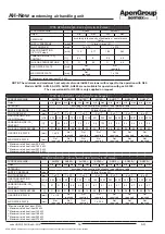
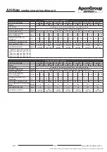
Perform the combustion analysis to verify that the level of CO
2
corresponds to the figures in the tables in Paragraph 6.7 "GAS
Settings Table"
If the measured value is different, turn the adjustment screw
on the Venturi pipe. Loosening the screw will increase the CO
2
level, screwing it down will decrease the level.
Set the heater to minimum output, and verify that the level of
CO
2
corresponds to the figures in the tables in Paragraph 6.7
"GAS Settings Table". If the values do not match, screw or
loosen the offset screw respectively to increase or decrease
the CO
2
level and repeat the procedure.
NOTE: The heater directly supplied to function with LPG
is set up for G31 gas. If the unit runs on G30 instead, it is
necessary to verify and possibly adjust settings for CO
2
as
shown in the tables in Paragraph 4.6 "GAS connection".

