APEN GROUP SPA reserves the right to make changes deemed to be required to its products or documentation
AH-New
condensing air handling unit
56
code HG0310.05GB ed.A-2010
AH
57
code HG0310.05GB ed.A-2010
AH
HG0131.00_IM_0002
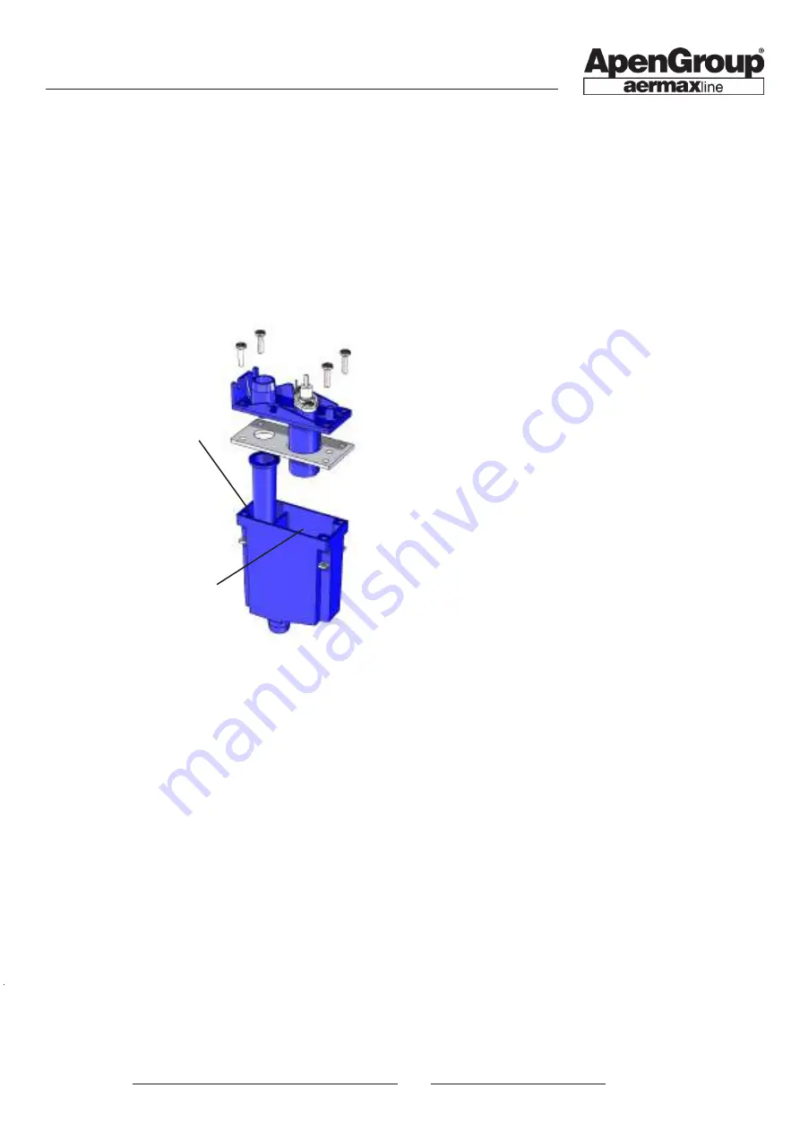
Main tank
Secondary tank
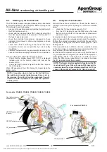
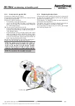
become necessary to clean the condensate collection trap, all
the gaskets inside it must be replaced.
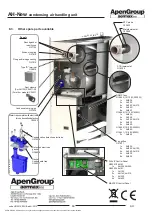
6) Condensate neutralisation vessel
To check that the salts inside the vessel are
still active, use litmus paper to check that the pH level of water
flowing out of it is greater than 6. If the pH is lower, replace the
calcium carbonate present in the vessel.
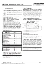
7) Inspection of intake gas pressure
Check that the intake pressure at the valve corresponds to the
value required for the type of gas that you are using.
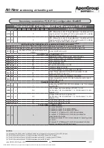
Verification to be performed with the burner on at the maximum
heat capacity.
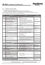
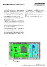
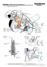
8) Inspection of flame monitoring equipment
With the burner running, close the gas valve and verify that the
machine is locked out, signalled on the LCD display of the CPU
PCB on board the machine with F10. Reopen the gas valve,
reset the lockout and wait for the burner to restart.
9) Inspection of the safety thermostat(s)
Operation to be performed with the AH unit operating and the
burner ON.
Open the thermostat series with an insulated tool [230 V],
remove the fast-on from the safety thermostat, wait for the
F20 block signal to appear on the LCD display on the CPU
PCB on the machine. Close again the thermostat series, then
reset the lockout.
As an alternative:
Operation to be preformed with AH unit OFF.
Disconnect the thermostat series with an insulated tool [230 V],
remove the fast-on from the safety thermostat, start the ignition
cycle and wait for the F22 block signal to appear on the LCD
display on the CPU PCB on the machine. Close the thermostat
series and check the fault reset.
10) Inspection of the ionization current
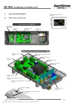
This procedure can be done directly from the LCD display by
entering into the I/O menu. The IOn parameter indicates the
value of the ionization current, and the reading is as follows:
•
100, indicates that the value is more than 2 microAmperes,
which is plenty for the equipment to function;
•
from 0 to 100, indicates a value from 0 to 2 microAmperes;
for example, 35 corresponds to 0.7 microAmperes, which is
the minimum threshold detectable for the flame monitoring
equipment.
The value of the ionisation current must not be below 2
microAmperes. Lower values indicate: the detection electrode in a
bad position, a rusted electrode or one about to stop functioning.
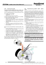
11) Inspection and cleaning of the fan compartment
Remove the rear access panel to the fan compartment and clean
any dirt accumulated inside the compartment itself.
12) Inspection and cleaning of the air fan protection grilles
Remove the rear access panel to the fan compartment and
clean any deposits around the fan intake protection grilles to
allow the air to flow well.
13) Inspection and cleaning of outdoor air intake plenum
(if any)
Remove the rear access panel to the outdoor air intake plenum
and remove any dirt accumulated inside the plenum itself.
14) Inspection and cleaning of outdoor air intake shutter
(if any)
Use a brush to remove any deposit around the outdoor air intake
shutter protection mesh and around the shutter itself to allow
the air to flow well.
5) Inspection and cleaning of the water trap
Clean the trap every year, and check the connections. Make
sure there are no traces of metallic residue. If metallic residue
has formed, increase the number of inspections.
Remove the cover retaining screws and clean the internal part
of the trap (it is possible to clean the trap under running water)
by checking that all ducts are free. Check the seal conditions.
Check the integrity of the detection electrode and use sandpaper
to remove any oxidation on the metal part.
Fill in the main tank with clean water and close the cover.
Reconnect the trap to the condensate drain system. Should it


