background image

C

H AP TER

 3.  S

Y STEM

 P

LA NNI NG

3–2

070-20000340-01 Rev A

Base Station Enclosure

 — The PacketWave Base Station Units must be

located indoors, generally within 50 meters (165 feet) of the outdoor radios and
antennas. (Greater cable lengths require insertion of dc from an external
source.) Ensure that an adequate room or closet is available, that it meets the
Base Station Unit environment specifications, and that sufficient power (120 or
220 V ac, or -48 V dc) is available.

Capacity and Equipment Requirements

 — PacketWave System capacity—

cell radius, sector and subscriber bandwidth, number of sectors, and number of
subscribers per sector—is discussed in Chapter 2 and summarized in 

Table3-A

.

Use this information along with expected subscriber requirements to plan cell
size, sectors, and base station equipment.

Radio Frequency Band

 — Determine the frequency band in which the system

will operate, and be sure that any required licences have been obtained. Make
sure that all PacketWave radio receivers and antennas you order are for the
proper frequency band.

Table3-A

PacketWave System Capacities

Parameter

Capacity

Cell radius

Up to 5 miles (8 km) with line-of-site transmission paths and typical configura-

tion, or 1 mile (1.6 km) with obstructed paths. Where even wider coverage is 

needed, the system can be configured to cover a radius of up to approximately 
30 miles (50,000 m).

Sectors per BSU

1 to 6.

Sector width

60° or 90°.

Subscribers per sector

Typically up to 250.

Total bandwidth

20 Mbps per sector; 120 Mbps per BSU.

Maximum bandwidth per sub-

scriber

Individually configured; from 384 kbps to 10 Mbps.

Bursts to 20 Mbps.

Upstream-to-downstream 

bandwidth ratio

From 90% downstream and 10% upstream, to 90% upstream and 10% down-
stream.

streamTj 108 0  TD5.1643  Tystem

Summary of Contents for PacketWave 1000 Series

Page 1: ...PACKETWAVE Fixed Wireless Broadband Access System PACKETWAVE 1000 SERIES BASE STATION EQUIPMENT Installation Configuration and Operation Manual 070 20000340 01 Rev A July 2001...

Page 2: ...to change Aperto PacketWave WaveCenter RapidBurst OptimaLink and ServiceQ are trademarks of Aperto Networks All other trademarks used herein are the property of their respective owners Aperto Networks...

Page 3: ...ion against harmful interference in a residential installation This equipment generates uses and can radiate radio frequency energy and if not installed and used according to the instructions may caus...

Page 4: ......

Page 5: ...he PacketWave System 2 1 Cell Size Capacity and Scalability 2 3 Multiple Frequency Bands 2 3 IP Based System 2 4 Range of Backhaul Options 2 4 Subscriber and Network Management 2 4 Technological Innov...

Page 6: ...d Subnetting 3 5 Configuration Planning 3 5 Service Level Planning 3 6 CHAPTER 4 INSTALLING BASE STATION UNITS Mounting 4 1 Front Panel Connections 4 2 Connecting the Radios to the BSU 4 2 Connecting...

Page 7: ...Parameters 6 17 General Parameters 6 17 Server IP Parameters 6 19 Bridging Clustering Parameters 6 19 Configuring SNMP Parameters 6 19 Configuring Email Alert Parameters 6 23 Subscriber Configuration...

Page 8: ...es the following information A QuickStart section for rapidly placing a PacketWave System in operation A conceptual overview of the PacketWave System Descriptions of the PacketWave hardware components...

Page 9: ...ointing hand icon as this paragraph is INTENDED AUDIENCE FOR THIS MANUAL This manual is intended for system designers and planners base station installers system operators and others requiring or desi...

Page 10: ...luding cables connectors mounts etc spe cifically rated for your particular environmental conditions and system performance requirements Always use appropriate tools and follow the instructions of the...

Page 11: ...PREFA CE xii 070 20000340 01 Rev A...

Page 12: ...ll be performed by qualified professionals following all safety and other requirements and acting in accordance with standard prac tices and procedures Failure to meet safety requirements and or non s...

Page 13: ...m cable length between subscriber Indoor Units bridge routers and Outdoor Units radio antennas is 165 feet 50 m without dc insertion from an external source Step 2 Define IP Networking A Each cell sec...

Page 14: ...Frequency mandatory iii If desired configure any optional WSS parameters as described in Chapter 6 of this manual iv Save the configuration by clicking the Generate WSS Config button and following the...

Page 15: ...by clicking on the Generate Configuration File button and following the prompts Save the config file with a name uniquely linking it to the subscriber Indoor Unit Aperto recommends the default format...

Page 16: ...ontrol interface on the Base Station has the same physical appearance as the 10 100Base T interface Make sure you connect to the right one Step 7 Install the Base Station Unit A Mount the Base Station...

Page 17: ...Installation Configu ration and Operation manual ii Make sure that the DHCP and TFTP servers are running iii Verify that the subscriber configuration file has been created and saved on the TFTP serve...

Page 18: ...tdoor Cat 5 male RJ45 connectors Radio Control connectors on the Outdoor and Indoor Units The Radio Control interface on the Indoor Unit has the same physical appearance as the 10 100Base T interface...

Page 19: ...sing a straight Ethernet cable for connection to a hub or a crossover Ether net cable for connection directly to a computer B Typically the only other thing necessary to connect a subscriber host comp...

Page 20: ...tem architecture functionality features benefits and hardware and software components CONCEPTUAL OVERVIEW OF THE PACKETWAVE SYSTEM Aperto Networks PacketWave System is a next generation fixed broadban...

Page 21: ...CHA PTER 2 PA CKETWA VE SY STEM OVER VIEW 2 2 070 20000340 01 Rev A Figure2 1 PacketWave System Elements...

Page 22: ...less network can grow to thousands of subscribers in urban or suburban areas through high frequency reuse and dense multicell deployment Combining high frequency reuse with advanced interference manag...

Page 23: ...ve solu tions to connect to backhaul networks In its basic configuration PacketWave 1000 supports 10 100 Mbps Ethernet This enables the PacketWave 1000 to connect directly to an Ethernet based MAN or...

Page 24: ...nology individually optimizes the reliability and throughput of each Subscriber wireless channel by dynamically adjusting up to ten PHY and MAC layer parameters The result is increased coverage extend...

Page 25: ...ns There are two models one with an ac power supply and one with a dc power supply Figure2 2 PacketWave 1000 Base Station Unit In the basic configuration pictured the PacketWave 1000 includes Four bui...

Page 26: ...ve additional subscribers providing a virtually unlim ited growth path To coordinate the Time Division Multiple Access TDMA and Time Division Duplexing TDD on which the PacketWave wireless communicati...

Page 27: ...s of radios for support of different frequency bands 2 5 GHz MMDS 3 5 GHz FWA 5 3 GHz U NII 5 8 GHz U NII Radio antenna units vary in size depending on the frequency band Each subscriber Indoor Unit c...

Page 28: ...are three models of the Indoor Unit the PacketWave 110 120 and 130 R1P1 supports only the PacketWave 130 which can function as either a bridge or a NAT router as illustrated in Figure2 4 Figure2 4 Pa...

Page 29: ...the DHCP server or a DHCP relay agent must be on the same subnet as the BSU s backhaul interface Access to a TFTP server identified by the DHCP server Each wireless interface is the gateway for a sub...

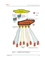
Page 30: ...2 11 070 20000340 01 Rev A CHA PTER 2 PA CKETWA VE SY STEM OVER VIEW Figure2 5 PacketWave System IP Architecture...

Page 31: ...CHA PTER 2 PA CKETWA VE SY STEM OVER VIEW 2 12 070 20000340 01 Rev A Figure2 6 PacketWave Subscriber Indoor Unit and Host IP Addressing...

Page 32: ...nt in the Base Station Unit Subscriber hosts can receive IP addresses in a variety of ways see Figure2 6 From the BSU s DHCP server via DHCP relay agents in the subscriber Indoor Unit and the Base Sta...

Page 33: ...e This is done during BSU configuration using the Wave Center Configuration Manager Figure2 7 shows multiple subnets on a wireless interface Note that when a sub scriber Indoor Unit uses DHCP to reque...

Page 34: ...ss can define a subnet meaning that subnets need not be limited to Class A B or C sizes Using VLSM addressing techniques such as recursive subnetting can simplify routing and allow more efficient use...

Page 35: ...face TFTP Server For the PacketWave System the main function of the TFTP server is to store the system configuration files and download them on request Each Base Station Unit and subscriber Indoor Uni...

Page 36: ...S server to be used in the resolution of Internet domain names SMTP Server The PacketWave Base Station Unit can use email to announce events If this feature is to be used an SMTP Simple Mail Transfer...

Page 37: ...CHA PTER 2 PA CKETWA VE SY STEM OVER VIEW 2 18 070 20000340 01 Rev A Figure2 9 PacketWave Servers and Management Access...

Page 38: ...er Configuration Manager CM is a Java based application used to configure PacketWave base station and subscriber equipment It runs on any of the following platforms Windows 98 Windows NT Windows 2000...

Page 39: ...ven in Chapter 8 of this manual SNMP Agents For real time monitoring and limited configuration each Base Station Unit and sub scriber Indoor Unit includes a built in SNMP agent with trap support In R1...

Page 40: ...QoS capability is based on sets of classifiers and service flows and links between the two as shown in Figure2 10 A classifier is one or more layer 2 and or layer 3 parameters which will identify a pa...

Page 41: ...CHA PTER 2 PA CKETWA VE SY STEM OVER VIEW 2 22 070 20000340 01 Rev A Figure2 10 PacketWave Service Levels...

Page 42: ...ennas at the base station and subscriber site performance is improved when transmission paths are unobstructed Do whatever is practical to minimize actual or potential transmission obstructions Antenn...

Page 43: ...size sectors and base station equipment Radio Frequency Band Determine the frequency band in which the system will operate and be sure that any required licences have been obtained Make sure that all...

Page 44: ...3 3 070 20000340 01 Rev A CHA PTER 3 SY STEM PLA NNING...

Page 45: ...onnecting the subscriber Indoor Unit to the outdoor radio antenna and for connecting the subscriber Indoor Unit to the subscriber s computer or LAN Table3 C identifies the cables that you will need to...

Page 46: ...dividual subscriber Indoor Units matched to subscriber site needed for DHCP configuration IP address for each subscriber Indoor Unit s wireless interface Default gateways for subscriber Indoor Units B...

Page 47: ...t and signifi cant expertise in quality of service QoS issues and techniques To maximize the flex ibility with which service levels can be defined and managed the PacketWave System includes extensive...

Page 48: ...4 F 0 and 40 C and the humid ity between 10 and 90 noncondensing MOUNTING The Base Station Unit occupies two vertical rack units 3 5 inches in a standard 19 inch equipment rack It includes integral mo...

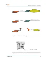
Page 49: ...Connecting the Backhaul Link The standard backhaul connection for the Base Station Unit is a 10 100 BaseTX link This can be used for a range of different backhaul implementations as shown in Figure4...

Page 50: ...4 3 070 20000340 01 Rev A CHAPTER 4 INSTA LLING BA SE STATION UN ITS Figure4 2 Backhaul Channel Examples Figure4 3 Backhaul Link Connection To Ethernet backhaul router...

Page 51: ...e alternate signal source can take over immediately To interconnect the multiple Base Stations 1 Determine the Base Stations which will be the main and alternate sync signal sources 2 For the main syn...

Page 52: ...cts Alt Sync Out on Alternate Master to Alt Sync In on all BSUs except Master Connects Main Sync Out on Main Master to Main Sync In on all BSUs 50 ohm terminations T connector T connector T connector...

Page 53: ...ot already present install the reference source per the manufacturer s instructions 2 Construct a coaxial cable with a the required connector for the reference source at one end a BNC T connector for...

Page 54: ...desired external alarm or control circuit 2 Use between 28 and 14 AWG wire 2 5 mm maximum diameter for connection to the BSU Wire may be solid stranded or stranded with ferrule 3 Verify whether the a...

Page 55: ...front panel as shown in Figure4 7 using a null modem crossover cable up to 25 feet in length Operation of the CLI which can also be accessed via Telnet is discussed in Chapter 8 of this manual Figure...

Page 56: ...Unit as illustrated in Figure4 8 For the US and other 120VAC power the fuse is a 4 A 250 V time lag high breaking fuse 5 x 20 mm such as the Schurter SPT 0001 2510 Should this fuse blow determine and...

Page 57: ...wire install a crimp style ring lug of 0 3 inches 7 5 mm or less in diameter to fit between the ter minal barriers Make sure the wires are marked or color coded to identify pos itive and negative conn...

Page 58: ...antenna mounting systems can be used for the PacketWave base station Choose a mounting system appropriate for your particular network and site and fol low the manufacturer s directions to install If t...

Page 59: ...Figure5 1 the bracket accomodates a pole diameter of 1 5 inches 3 8 cm 2 inches 5 cm To mount an antenna 1 Determine the mounting location for the antenna 2 Orient the antenna vertically 3 Using the...

Page 60: ...nd a control cable These cables run from out door radios to the indoor BSU so a suitable cable run and building entry point must be identified as discussed in Chapter 3 Connections to the BSU are illu...

Page 61: ...CHA PTER 5 INSTA LLING RAD IOS AN D ANTENN AS 5 4 070 20000340 01 Rev A Figure5 2 Radio Cables for Connection to Antenna Figure5 3 BSU Radio Connections Control cable to radio Signal cable to radio...

Page 62: ...U to the radio Include a service drip loop as appropriate 2 Install a male F connector at the radio end of the cable 3 Attach the cable to the female F connector on the radio as shown inFigure 5 4 4 D...

Page 63: ...RJ45 male connector on the radio end of the cable 4 Plug the cable into the RJ45 socket on the radio as illustrated in Figure5 4 5 Put the rubber boot in position to protect the RJ45 connection and s...

Page 64: ...rce capable of supplying 1 5 A a coaxial bias tee with two female F connectors and one BNC connector and a short coaxial cable with a male F connector at each end 2 Connect the short coaxial cable to...

Page 65: ...CHA PTER 5 INSTA LLING RAD IOS AN D ANTENN AS 5 8 070 20000340 01 Rev A...

Page 66: ...is the configuration of the IP network including the DHCP server described in Chapter 7 INSTALLING THE WAVECENTER CONFIGURATION MANAGER The WaveCenter Configuration Manager is provided on CD as part...

Page 67: ...ry which contains the Configuration Manager installation files and a jre folder directory which contains the executable file for the Java Runtime Environment 2 If the computer does not already have th...

Page 68: ...ation unit and subscriber site CPE must have a valid configuration file in order to function BSU and Subscriber Branches The WaveCenter Configuration Manager consists of separate Base Station Unit and...

Page 69: ...ration Manager Screen Elements Configuration Screen Formats Each branch of the WaveCenter Configuration Manager BSU and subscriber CPE consists of multiple configuration menu screens identified and ac...

Page 70: ...anager Save Instance Icon Used to save a particular instance as configured on this menu for example an SNMP manager Restore Defaults Icon Used to restore factory defaults for the parameters on the pag...

Reviews: