4–7
070-20000340-01 Rev A
C
H APTER
4. I
NSTA LLI NG
B
A SE
S
TATIO N
U
N ITS
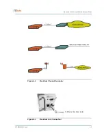
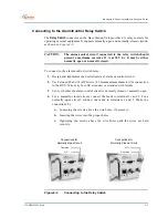
Connecting to the Alarm/Control Relay Switch
The
Relay Switch
connector on the Base Station Unit provides dry relay contacts for
operating external equipment. It supports normally-open and normally-closed circuits,
as shown in
Figure4-6
.
CAUTION:
The alarm/control circuit connected to the relay switch should
present a maximum current of 2 A at 30 V dc. It may be either
normally open or normally closed.
To connect to the alarm/control switch relay:
1.
Design and implement the desired external alarm or control circuit.
2.
Use between 28 and 14 AWG wire (2.5 mm maximum diameter) for connection
to the BSU. Wire may be solid, stranded, or stranded with ferrule.
3.
Verify whether the alarm/control circuit is normally closed or normally open.
4.
For a normally-closed circuit, connect the leads to terminals 1 and 2. For a
normally-open circuit, connect the leads to terminals 2 and 3. Make the
connections by:
a.
Loosening the screws above the wire holes, if necessary.
b.
Inserting the wires into the proper holes.
c.
Tightening the screws above the wire holes until the wires are held
securely.
Figure4-6
Connecting to the Relay Switch
Connections for
Normally-Open Circuit
Connections for
Normally-Closed Circuit
Common
Common
N.C.
N.O.


