5–3
070-20000340-01 Rev A
C
H APTER
5. I
NSTA LLI NG
R
AD IO S
AN D
A
NTENN AS
R
UNNING
THE
R
ADIO
C
ABLES
Connections to the radio include two “RF jumper” connections “up” to the antenna
and two connections “down” to the Base Station Unit.
Radio to Antenna
The radio is connected to the antenna by two cables. One end of each is attached to
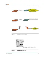
the radio internally, and the other terminates with a male N connector, as shown in
Figure5-2
.
To connect the radio to the antenna:
1.
Connect the cables from the radio to the appropriate connectors on the antenna.
2.
Apply a silicone sealant or other weatherproofing to the connections as desired.
Radio to Base Station
There are two cables that connect each radio to its Base Station Unit: a radio signal
cable (which also carries dc power) and a control cable. These cables run from out-
door radios to the indoor BSU, so a suitable cable run and building entry point must
be identified, as discussed in Chapter 3. Connections to the BSU are illustrated in
Figure5-3
; Connections to the radio are illustrated in
Figure5-4
.
For these outdoor-to-indoor connections, the order of the steps in the installation
procedure will vary depending on a number of factors, including site particulars
and installers’ preferred practice. For example, in some cases it may be best to
run unterminated cable and then attach connectors; in others it may be more effi-
cient to attach one or both connectors to the cable before running it. Also, cable
dressing at various locations may be best performed at different points in the pro-
cedure. Therefore, the procedures given for radio-to-BSU connections should be
taken as a list of necessary steps and a suggested order, and modified as appro-
priate for your particular circumstances.

