Commissioning
15
Safety instructions
Caution!
After installation of the operator, the person responsible
for the installation must complete an EC declaration
of conformity for the door system in accordance with
Machinery Directive 2006/42/EC and apply the CE mark and
a type plate. This is also required for private installations
and also if the operator is retrofi tted to a manually operated
door. This documentation and the installation and operating
manual are retained by the operator.
Caution!
The adjustment of the force tolerance is safety-relevant and
must be performed by qualifi ed personnel with the utmost
care. If the adjustment of the spring unit is excessively high,
people or animals could be injured and objects damaged.
Select a force tolerance that is as low as possible so that
obstacles are detected quickly and safely.
Caution! Danger of falling!
In an emergency release the door could independently open
or close itself due to a broken spring or incorrect setting
of the weight balancing.
The operator could be damaged or destroyed.
Adjust door end positions
for CLOSE + OPEN
Caution!
Make sure the travel path of the operator is free of obstacles.
Obstacles (e.g. cross beams between the rails of the door)
damage the operator and must be removed properly before
commissioning.
Caution!
Check the following:
• Have all mechanical door locks been removed?
• Can the emergency release be activated from outside
using a Bowden cable or release lock?
Important information!
When opening and closing the door manually, do not operate
it with the operator engaged.
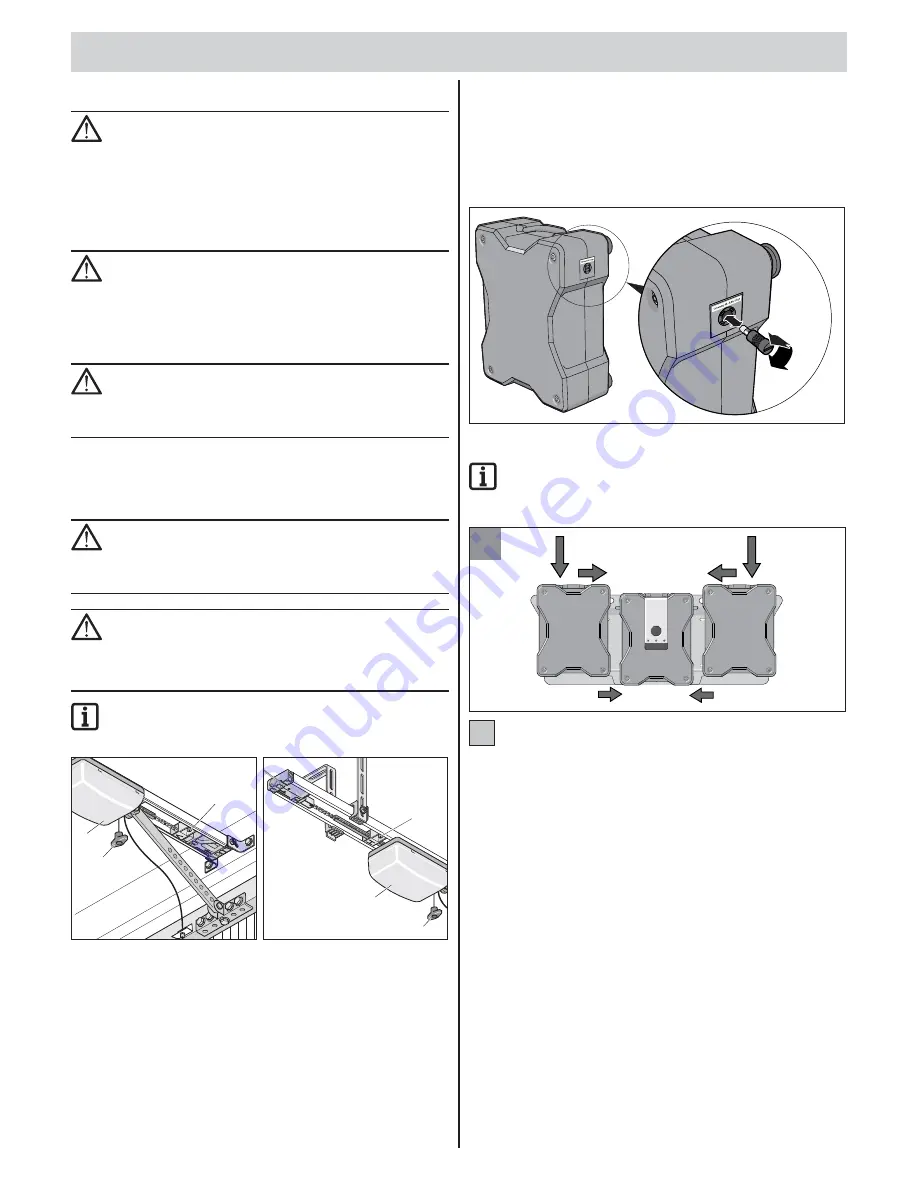
V
N
1
H
1
N
Door CLOSE end position
•
Unlock the carriage, if it is not already unlocked. Pull once on the
emergency unlocking cord (N). It should be possible to manually
push the carriage back and forth.
•
Close the door by hand.
•
Loosen the guide idler (V) and push it toward the carriage until it clicks
(end switch switches), then screw the guide idler (V) in tight.
Door OPEN end position
•
Open the door by hand.
•
Loosen the guide idler (H) and push it toward the carriage until it clicks
(end switch switches), then screw the guide idler (H) in tight.
•
Close the door by hand.
Putting the battery units
into operation
Inserting fuses
Insert supplied glass tube fuses (T 6 A) into the fuse holders on the outside
of the battery units.The right-hand battery unit is pictured; the left side
corresponds to the illustration.
Attaching the battery units to the support rail
Important information!
The support rail must be assembled so it is absolutely
horizontal for it to function perfectly. Attach the battery
units so that the fuse is located on the outside.
24
• The left and right battery units are attached from above and
pushed together with the control unit.
• If the red LEDs do not stop blinking a few seconds after attaching,
no contact exists.
24
Commissioning


