21
Extended functions and connections
General information
Caution!
The activities described in the chapter “Extended functions
and connections” must only be performed by qualifi ed
electricians.
• As delivered, the DIP switches are set to the “OFF” position,
all additional functions are switched off.
Important information!
Connecting additional consumers (e.g. photo eyes) increases
energy consumption, thereby decreasing the number
of cycles per battery charge.
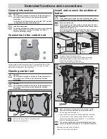
Connection to the control unit
2
3
1
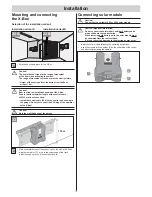
The connections for the track supply line (1) and the Würth Solar CIS
fi
x
solar module (2) as well as two openings (3) for inserting other cables
are located on the bottom of the control unit.
Opening control unit
Caution!
The activities described in the chapter “Extended functions
and connections” must only be performed by qualifi ed
electricians.
Caution!
The activities described in the chapter “Extended functions
and connections” must only be performed by qualifi ed
electricians.
2
1
25
• Remove the four screws (1) on the front side.
• Remove front housing (2).
Install and connect the additional
button
Caution!
When actuating the button, the drive must keep clear of the
movement zone of the door and must have a direct view of it.
Important information!
Only necessary if an extra button is required apart from the
integrated button. An additional button cannot be connected
together with a photo eye.
Only use the connection for potential-free closer contacts.
External voltage can damage or destroy the control unit.
min. 1,6 m
26 A
min. 1,6 m
26 B
• Permanently install the button cable.
• Install the button in a suitable, easily accessible position
in the garage. Minimum height above the ground: 1.6 m
• Install the button cable in the garage.
Connect the end of the cable to the button.
• Open the control unit as described in the previous chapter.
Have you noted the position of the plug and boards?
• Pull the plug of the
fl
at cable (3).
• Insert the M8 cable gland into the opening on the underside
of the control unit. Lead through cable, relieve from strain.
• Connect the button cable (8) to terminals 1 + 2 of the small
board (9). Important information!
Connect any existing key switch (potential-neutral closer
contact) in parallel to terminals 1 + 2 of the small board (9).
•
Reconnect the plug of the
fl
at cable (3).
•
Attach front housing (2) and fasten.
25
26
8
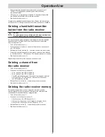
9
27
27


