Extended functions and connections
22
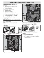
Obstacle detection
(DIP 1, 2 + 3)
DIP switch 1:
OFF
No reaction during an interruption of a safety input.
The door stops during a power cut-off.
ON
The operator stops the door.
DIP switch 2: Safety connection function
OFF
NC contact for photo eye
ON
Button connection for button 2
(partial opening, de
fi
ned opening and closing)
DIP switch 3: behaviour of operator when the door closes.
OFF
Operator stops and opens the door slightly, reversion
ON
The operator stops and opens the door completely.
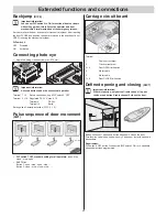
Connect button 2
(DIP 2)
Caution!
Only use the connection for potential-free closer contacts.
External voltage can damage or destroy the control unit.
Important information!
A safety connection is no longer available.
A photo eye cannot be connected in parallel.
Button 2 can be used as needed for the following functions:
– De
fi
ned opening and closing
– Partial opening
•
Approved wiring cross-section: max. 0.75 mm².
8 9
10 1
1 12
7
2
1
ON
DIP
3 4
5 6
8
7
•
Remove jumper (1) from terminal 7 and 8,
DIP switch 2 ON
.
2
•
Reinsert loose cable (2) into terminal 7.
3
4
•
Fasten cable from button 2 (3) from the small board in position 3 + 4.
Connect warning light (DIP 4)
8 9
10 11
12
7
2
1
ON
DIP
3 4
5 6
8
7
•
Approved wiring cross-section: max. 0.75 mm².
Terminal 11 + 12 unregulated DC 24 V (max. 34 V), max. 1 A
DIP switch 4
OFF
Connected warning light is blinking
(controller generates blinking)
ON
Door status display | Door status display | Door status indicator
– Lights up if the door is not closed
– Is off if the door is closed

