27
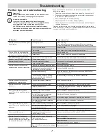
Troubleshooting
Malfunction
Possible cause
Corrective action
Operator does not function and lights
do not light up.
No voltage present.
Attach XLR plug.
Check batteries (check state of charge (LEDs)); are the battery
units correctly attached? (Check glass tube fuse in battery units)
No control unit installed.
Install controller.
Solar module.
Check solar module (plug/alignment/contamination...).
The red LED in the light
fi
eld of the
control unit continues to
fl
ash although
the battery unit has been attached.
Battery unit empty.
Charge battery unit.
Contact faulty.
Check contact, adjust the support rail if applicable.
Red LED behind the rubber cover
fl
ashes in “door CLOSE” end position.
Operator has not been programmed,
no force values stored.
Program the operator. See chapter “Commissioning”.
Operator doesn't function.
Controller incorrectly installed.
Plug the control unit correctly into the connector.
Photo eye interrupted.
Remove interruption.
Operator does not function when
operated with a handheld transmitter.
Battery in the handheld transmitter is
fl
at.
Replace battery with new one.
The handheld transmitter has not been
programmed for the radio receiver.
Program handheld transmitter.
Incorrect radio frequency.
Check the frequency (40 MHz with wire antenna, 868/434 MHz
without external antenna).
The command is constantly pending
because the button of the handheld
remote control is stuck.
Release the key or exchange the handheld transmitter.
Operator does not function when
operated by an external button.
Button not connected or defective.
Connect button or replace it.
Operator does not end programming
procedure.
End positions incorrectly adjusted.
Adjust end positions, see chapter “General commissioning”.
Afterglow time too short.
To extend the afterglow time, see “Setting the afterglow time
of the LED lighting”.
Door stops while closing, moves
about 10 cm in the opposite direction,
and stops.
Actuation of the force cut-off due
to an obstacle.
Remove obstacle, open door completely.
Incorrect force values programmed
or force tolerance set too low.
Wipe force values and teach again
Switch-trigger incorrectly adjusted.
Adjust switch-trigger, see chapter “Adjusting end switches”.
Door incorrectly adjusted or defective
(e.g. spring shaft).
Have door adjusted or repaired by a technician.
Door stops while opening, moves
about 10 cm in the opposite direction
and stops.
Force cut-off actuated by an obstacle.
Remove obstacle, open door completely.
incorrect force values programmed
or force tolerance too low
Delete force values and reprogram.
Guide idler incorrectly adjusted.
Adjust switch-trigger, see chapter “Adjusting end switches”.
Door stops while opening.
Connected photo eye interrupted
and DIP switch 1 is ON.
Eliminate interruption or turn DIP switch 2 to OFF.
Operator does not close the door.
Photo cell power supply interrupted.
Check connection.
Operator
opens
the door and then
does not respond to a command from
the handheld transmitter or the button.
Safety input tripped
(e.g. photo eyes defective).
Remove obstacle from photo eyes.
Repair photo eyes.
Direct connector not properly plugged in.
“Door CLOSE” end switch in the carriage
defective.
Replace end switch.
Further tips on troubleshooting
Important!
Many malfunctions can be resolved by a control unit reset
(delete force values), then reprogram the operator.
HomeLink-compatible
If your vehicle is equipped with a HomeLink system
(Version 7), our operator and radio receiver with 868.6 MHz
are compatible. Another radio frequency (40.685 or
434.42 MHz) must be used with older HomeLink systems.
Information can be found under http://www.eurohomelink.com
or contact your specialist dealer.
If you cannot
fi
nd the malfunction in the table and eliminate it, take
the following actions:
•
Perform a control unit reset (delete force values) on the control unit.
•
Disconnect connected accessories (e.g. photo cells) and reconnect
the jumper for a safety connection.
•
Set all DIP switches to the factory setting.
•
Set potentiometer to the factory setting, if present.
•
Check all connections on the direct connectors and terminal strip and
retighten if necessary.
Operator malfunctions can be corrected according to the following table.
If this does not help, contact your specialist dealer for assistance or consult
our website at http://aperto-torantriebe.de

