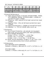
3.Overall Performance:
3.1 Total Output Power: Full load (ATX-WA750W: 750W;
ATX-WA900W: 900W; ATX-WA1100W: 1100W) at
normal line input voltage.
3.2 Efficiency: 80% typical at full load normal line input
voltage.
3.3 Hold Up Time: 17ms at full load normal line input
voltage.
3.4 Switching Frequency: 125KHz at normal line input.
3.5 Stability: +/- 5% for 24KHR after warm up.
C o l o r
S in g le
P i n
B la c k
C O M
1
B la c k
C O M
2
B la c k
C O M
3
B la c k
C O M
4
B la c k
C O M
5
Y e llo w
+ 1 2 V 3 / + 1 2 V 4
6
Y e llo w
+ 1 2 V 3 / + 1 2 V 4
7
Y e llo w
+ 1 2 V 3 / + 1 2 V 4
8
C o l o r
S in g le
P i n
Y e llo w
+ 1 2 V D C
1 - 3
B la c k
C O M
4 - 6
R e d
+ 5 VD C
7 - 9
B la c k
C O M
1 0 - 1 2
O ra ng e
+ 3 . 3 V D C
1 3 - 1 5
USER’S MANUAL
1.Product Features.............................
2.Product Specifications......................
3.Overall Performance........................
4.Protection......................................
5.Dimensions....................................
6.Description of Connectors.................
7.Precautions.....................................
8.Information....................................
9.Overview of Connectors...................
CONTENTS
This power supply unit is designed to be functional and
appealing. Only high quality material and components
are used to assure superior performance, reliability and
stability. A good power supply need not only reliable and
efficient, it can also be a piece of art to delight our
hearts!
1.Product Features:
1.1 High-tech black titanium coated case.
1.2 Multi-color coated components & class-fibrous PCB
to avoid warping.
1.3 Fan LED color switch with 5 mode choices.
LEDs can be switched to red, blue, green, auto-
color and off.
1.4 Excellent design of single 13.5cm ball bearing crystal
LED fan to enhance cooling of effective areas.
1.5 Cable Management: All cables are sleeved to avoid
clutter and improve airflow.
1.6 UV sensitive On/Off power switch, power plug and
connectors.
1.7 Fire-resistant acrylic windows to allow viewing of
power supply internals.
1.8 Quad 12V Rails for ATX V2.2 and EPS 12V V2.92
application.
1.9 Supports NVIDIA SLI.
1.10 Supports ATI Cross Fire.
1.11 Supports Dual/Quad Core CPUs.
1.12 Supports Intel and AMD systems.
1.13 Highly efficient circuit design.
1.14 Thermally controlled automatic sensor to regulate
fan speed and reduce noise.
1.15 Short Circuit/Over Voltage/Over Current/Over Power
/Over Temperature/Under Voltage Protection.
1
1.16 Approved by UL, CUL, TUV, CE, CB.
1.17 100% Burn-In Test/Hi-Pot Test/Vibration test/Leak
Current Test.
1.18 Connectors:
1 x 20/24Pin Main Power Connector
1 x 4/8Pin +12V and EPS Connector
8 x 4Pin Peripheral Connector
2 x 4Pin Floppy Connector
2 x 6Pin PCI-Express Connector
2 x 8Pin PCI-Express Connector
6 x Serial ATA Connector
2.Product Specifications:
2.1 AC Input Voltage: 115V/230V
2.2 AC Input Frequency: 60Hz/50Hz
2.3 Operating Temperature: The power supply should
be operated in an ambient temperature of 0ºC~
40ºC.
2
DC Output: ATX-WA750W
D C
O u t p u t
Max Curre nt
2 5 A
3 0 A
2 5 A
2 5 A
2 5 A
2 5 A
0 . 6 A
3 . 0 A
M i n . C u r re n t
0 . 5 A
0 . 3 A
0 . 5 A
0 . 5 A
0 . 5 A
0 . 5 A
0 A
0 A
C o m b i n e d P o w e r
7 . 2 W
1 5 W
T O T A L
M A X . 1 5 0 W
M a x . 6 4 8 W ( 5 4 A )
7 5 0 W
+ 1 2 V 3
+ 1 2 V 4
- 1 2 V
+ 5 V S B
+ 3 . 3 V
+ 5 V
+ 1 2 V 1
+ 1 2 V 2
D C
O u t p u t
Max Curre nt
2 5 A
3 0 A
2 8 A
2 8 A
2 8 A
2 8 A
0 . 6 A
3 . 0 A
M i n . C u r re n t
0 . 5 A
0 . 3 A
0 . 5 A
0 . 5 A
0 . 5 A
0 . 5 A
0 A
0 A
C o m b i n e d P o w e r
7 . 2 W
1 5 W
T O T A L
M A X . 1 6 0 W
M a x . 7 4 4 W ( 6 2 A )
9 0 0 W
+ 1 2 V 3
+ 1 2 V 4
- 1 2 V
+ 5 V S B
+ 3 . 3 V
+ 5 V
+ 1 2 V 1
+ 1 2 V 2
DC Output: ATX-WA900W
DC Output: ATX-WA1100W
3
4.Protection:
4.1 Over Power Protection: all outputs are equipped
with short circuit and 150% over load protection.
4.2 Over Voltage Protection:
3.3V = 3.9V Min. ~ 4.5V Max.
5V = 5.7V Min. ~ 6.5V Max.
12V = 13.3V Min. ~ 14.5V Max.
4.3 Short Circuit Protection: 3.3V, +5V, +12V
are all protected by short circuit protection.
5.Dimensions:
ATX-WA750W & ATX-WA900W:
150mm x 150mm x 85mm(5.9” x 5.9” x 3.4”)W x L x H
ATX-WA1100W:
150mm x 170mm x 85mm(5.9” x 6.7” x 3.4”)W x L x H
P
12
P
21
P
20
P
19
P
18
P
1
7
P
16
P
15
P
14
P
13
P
10
P
8
3
2
1
5
4
3
2
1
5
4
4
5
1
2
3
P2
P1
P3
P4
22
23
24
10
11
12
17
19
18
20
13
14
15
16
4
3
6
5
7
8
1
2
21
9
P7
P6
P5
3
2
1
5
4
4
5
1
2
3
4
5
1
2
3
P
9
P
11
P
22
6.Description of Connectors:
DC OUTPUT WIRES:
4
ATX Main Power Connector 24PIN(20+4PIN):
C o l o r
Sin gle
P i n
C o l o r
Sin gle
P i n
O r an g e
(Bro wn )
O r an g e
+ 3 . 3 V
2
B l ue
- 1 2 V D C
1 4
B l ac k
C O M
3
B l ac k
C O M
1 5
R e d
+ 5 V D C
4
G r e e n
P S - O N
1 6
B l ac k
C O M
5
B l ac k
C O M
1 7
R e d
+ 5 V D C
6
B l ac k
C O M
1 8
B l ac k
C O M
B l ac k
C O M
S E N S E
G r ay
P W R _ O K
8
W h ite
-5VD C
2 0
P u r p l e
+ 5 V S B
9
R e d
+ 5 V D C
2 1
Ye llow
+ 1 2 V 1 D C
1 0
Ye llow
+ 5 V D C
2 2
Ye llow
+ 1 2 V 1 D C
1 1
Ye llow
+ 5 V D C
2 3
O r an g e
+ 3 . 3 V D C
1 2
B l ac k
C O M
2 4
+ 3 . 3 V D C
1 3
7
B l ac k
C O M
1 9
O r an g e
+ 3 . 3 V
1
P1
P2~P7
5
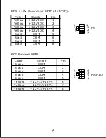
EPS +12V Connector 8PIN(4+4PIN):
C o l o r
S in g le
P i n
Y e llo w
+ 1 2 V 2 D C
1
Y e llo w
+ 1 2 V 2 D C
2
Y e llo w
+ 1 2 V 2 D C
3
Y e llo w
+ 1 2 V 2 D C
4
B la c k
C O M
5
B la c k
C O M
6
B la c k
C O M
7
B la c k
C O M
8
1
2
3
7
6
5
8
4
P8
PCI Express 8PIN:
4
8
5
6
7
3
2
1
P9/P10
6
C o l o r
S in g le
P i n
B la c k
C O M
1
B la c k
C O M
2
B la c k
C O M
3
Y e llo w
+ 1 2 V 3 / + 1 2 V 4
4
Y e llo w
+ 1 2 V 3 / + 1 2 V 4
5
Y e llo w
+ 1 2 V 3 / + 1 2 V 4
6
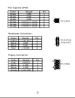
PCI Express 6PIN:
6
4
1
3
P11/P12
Peripheral Connector:
C o l o r
S in g le
P i n
Y e llo w
+ 1 2 V 1 D C
1
B la c k
C O M
2
B la c k
C O M
3
R e d
+ 5 V DC
4
4
1
P13~P16
P18~P21
Floppy Connector:
C o l o r
S in g le
P i n
R e d
+ 5 V DC
1
B la c k
C O M
2
B la c k
C O M
3
Y e llo w
+ 1 2 V 1 D C
4
P17/P22
7
7. Precautions:
Warning! To avoid the risk of electrical shock,
unauthorized persons should heed the following
precautions:
7.1 Do not open the power supply case!
7.2 Before powering on , please make sure that the
red RMS switch on the power supply corresponds
with the AC voltage given in your environment.
(USA & Canada: 115V; Europe, Central and South
America: 230V).
*This applies to the 750W version only.
*The 900W and 1100W versions are equipped
with PFC and do not require this procedure.
7.3 Avoid exposure to humidity.
8. Information:
Thank you for purchasing a high-quality Apevia product!
Please visit our website at http://www.apevia.com for
complete warranty information and future support for
your product. For the latest release information, or
should you have any questions, please visit our website,
or contact us at:
Support Phone Number: 1-909-718-0789
Support E-mail: support@apevia.com
8
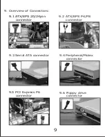
9. Overview of Connectors:
9.1 ATX/EPS 20/24pin
connector
9.2 ATX/EPS P4/P8
connector
9.3 Serial ATA connector
9.4 Peripheral/Molex
connector
9.5 PCI Express P6
connector
9.6 Floppy drive
connector
9
Serial ATA Connector:
1
2
3
3
3
4
8
8
9
D C
O u t p u t
Max Curre nt
2 5 A
3 0 A
3 0 A
3 0 A
3 0 A
3 0 A
0 . 6 A
3 . 0 A
M i n . C u r re n t
0 . 5 A
0 . 3 A
0 . 5 A
0 . 5 A
0 . 5 A
0 . 5 A
0 A
0 A
C o m b i n e d P o w e r
7 . 2 W
1 5 W
T O T A L
+ 1 2 V 2
M A X . 1 7 0 W
M a x . 9 1 2 W ( 7 6 A )
1 1 0 0 W
+ 1 2 V 3
+ 1 2 V 4
- 1 2 V
+ 5 V S B
+ 3 . 3 V
+ 5 V
+ 1 2 V 1
Summary of Contents for ATX-WA1100W
Page 1: ...USER S MANUAL ...
Page 12: ......


