background image

EK76                              

2

EK76U Rev A

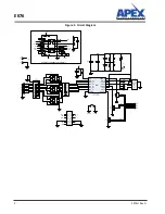
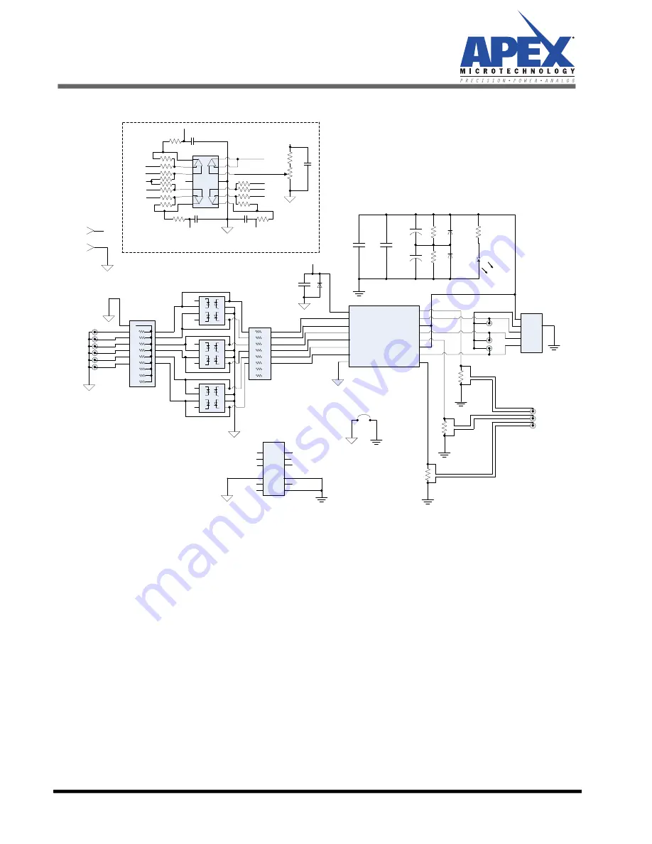
 Figure 1: Circuit Diagram 

DUT

Vcc

INW_HS

INW_LS

INV_HS

INV_LS

INU_HS

INU_LS

DGND

PGND_W

OUT_W

+VS_VW

OUT_V

PGND_V

+VS_U

OUT_U

PGND_U

R3

HS,CSR

R2

HS,CSR

R1

HS,CSR

+Vs

PGND

W

V

U

P5

P3

P4

8
7
6
5
4
3
2
1

IMON_V

IMON_U

IMON_W

9

10
11
12
13
14
15
16

INW_H

INW_L
INV_H

INV_L

INU_H

INU_L

P14
P13
P12
P11
P10

P9

P8
P7
P6

P1

1

3

5

7

9

11

13

15

2

4

6

8

10

12

14

16

INU_H

INV_H

INW_H

IM_U

IM_W

INU_L

INV_L

INW_L

IM_V

P2

V

CC

CBP1

D1

CBP3

CBP2

CBP5

CBP4

R4

R5

D2

D3

1

2

3

4

5

6

7

8

9

10

R6-

socket

1

2

3

4

5

6

7

8

16

15

14

13

12

11

10

9

R7

J1

Press-Fit Sockets – 

90 mil PTH ±2 mil

+

+

R8

LED1

V

CC

P16

P15

DGND

PGND

8

7

6

5

1

2

3

4

V

CC

V

CC

8

7

6

5

1

2

3

4

V

CC

V

CC

8

7

6

5

1

2

3

4

V

CC

V

CC

R9

+

-

+ -

+

-

+ -

V+

V-

1
2
3
4
5
6
7

14
13
12
11
10

9
8

R10
R11
R12

R17

R18

R19

R20

R14
R15
R16

R13

V

CC

R21

R22

V

CC

BIAS

BIAS

BIAS

GNDU

IMONU

IMONV

GNDV

GNDW

IMONW

R24

C2

CURRV

CURRU

R23

C1

R25

C3

CURRW

C4

U1

D4

D5

D6

OPTIONAL CURRENT SENSE CIRCUIT

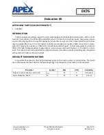
Summary of Contents for EK76

Page 1: ...andard pin header or SMA connectors A remov able 50 Ω termination resistor is offered for impedance matched inputs Coaxial measurement points are offered for high fidelity waveform measurement so erroneous overshoot ringing are cut down to a mini mum The layout is carefully optimized for signal and power transmission while permitting easy integration with system controllers and 3 phase loads ABSOL...

Page 2: ... 8 10 12 14 16 INU_H INV_H INW_H IM_U IM_W INU_L INV_L INW_L IM_V P2 VCC CBP1 D1 CBP3 CBP2 CBP5 CBP4 R4 R5 D2 D3 1 2 3 4 5 6 7 8 9 10 R6 socket 1 2 3 4 5 6 7 8 16 15 14 13 12 11 10 9 R7 J1 Press Fit Sockets 90 mil PTH 2 mil R8 LED1 VCC P16 P15 DGND PGND 8 7 6 5 1 2 3 4 VCC VCC 8 7 6 5 1 2 3 4 VCC VCC 8 7 6 5 1 2 3 4 VCC VCC R9 V V 1 2 3 4 5 6 7 14 13 12 11 10 9 8 R10 R11 R12 R17 R18 R19 R20 R14 R1...

Page 3: ...TP TVS diode 23 1V standoff 5W 1 D2 3 P6KE400A TVS diode 342V standoff 5W 2 D4 5 6 UC3611N Diode 4 array 50V 3A 3 LED1 LTL2R3KRD EM LED red 2mA nominal 1 Hardware DUT socket 6342 0 15 15 42 27 10 0 Pin Receptacle 20A 16 P1 TS01 5 Block Terminal Strip 1 P2 M20 9980845 Pin header 2 x 8 0 1 pitch 1 P3 4 5 731711900 BNC connector vertical PC mount 3 P15 16 571 0100 Banana Jack horizontal PC mount 2 DU...

Page 4: ... hole 1 C1 2 3 CAP 0805 Not Populated 3 C4 C0805C104M5RACTU CAP 0805 100nF 50V X7R 1 R9 12 13 16 17 20 ERA 6AEB4992V RES 0805 49 9kΩ 1 8W 0 1 6 R10 11 14 15 18 19 ERA 6AEB103V RES 0805 10kΩ 1 8W 0 1 6 R21 RMCF0805JT39K0 RES 0805 39kΩ 1 8W 5 1 R22 3386P 1 103LF Trimmer 10kΩ Through hole 1 R23 24 25 RMCF0805ZT0R00 RES 0805 0Ω Jumper 3 ...

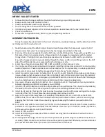
Page 5: ...aller components including R4 8 D1 6 LED1 and P2 Note that R6 includes a socket to eas ily swap between high impedance inputs R6 not installed and 50 Ohm terminated inputs R6 installed Each element of this resistor can dissipate up to 200mW Match the direction of R6 with the PCB designa tor when installing Also match all diode orientations with their respective designators 6 Use a piece of heavy w...

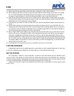
Page 6: ... the DUT will go Place the DUT in this space so its pins pass through the TW22 and the heatsink slots Rest the pins over the pin receptacles from step 2 Engaging all 16 receptacles requires much force Rather than applying this force by hand reinstall the 6 32 x screws and nuts this time passing through the DUT tabs and TW22 With the 6 32 nut on the component side tighten the screws in small increm...

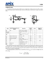
Page 7: ... shown on the Voltmeter The following equation represents the Low Side Phase Current IPHASE as a function of voltage measured at IM_X VM Value Applicable Designatorson EVAL94 Equation Default Value Units Suggested Tolerance VOS Bias ADC min input or higher 1 65 V VOUT_MAX ADC max input or lower 3 3 V IOUT_MAX 80 A 33 A Gain VOUT_MAX VOS IOUT_MAX 10 mΩ 5 V V RF R9 12 13 16 17 20 1 8k RF 100k 50k Ω ...

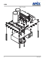
Page 8: ...EK76 8 EK76U Rev A Figure 2 Top View ...

Page 9: ...EK76 EK76U Rev A 9 Figure 3 Bottom View ...

Page 10: ... for resale APEX MICROTECHNOLOGY PRODUCTS ARE NOT DESIGNED AUTHORIZED OR WARRANTED TO BE SUITABLE FOR USE IN PRODUCTS USED FOR LIFE SUPPORT AUTOMOTIVE SAFETY SECURITY DEVICES OR OTHER CRITICAL APPLICATIONS PRODUCTS IN SUCH APPLICATIONS ARE UNDERSTOOD TO BE FULLY AT THE CUSTOMER OR THE CUSTOMER S RISK Apex Microtechnology Apex and Apex Precision Power are trademarks of Apex Microtechnology Inc All ...

Reviews: