12
Installing/Replacing Sanding Belt
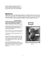
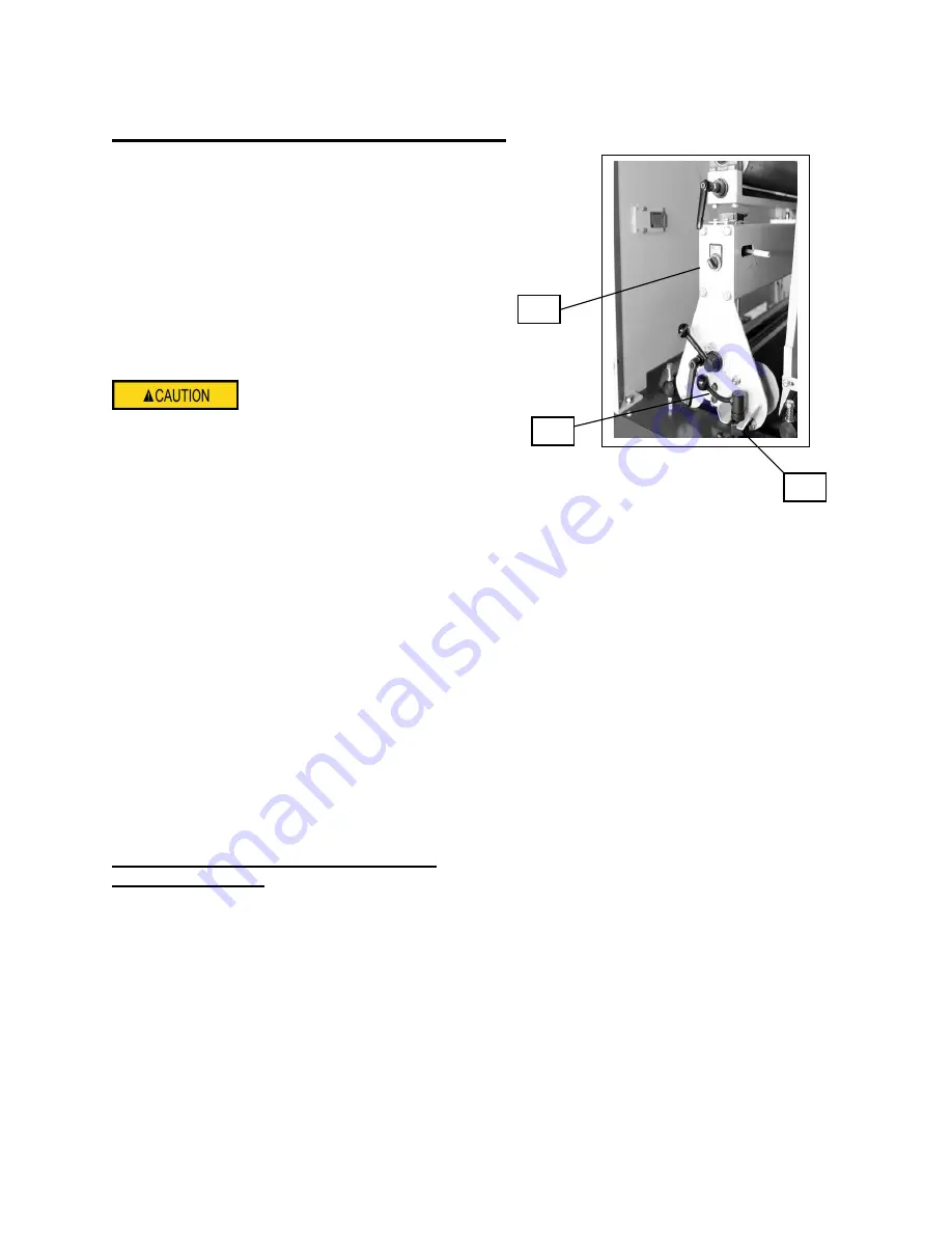
1. Machine should be disconnected from
power source.
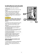
2. Turn the air valve switch (A, Figure 3) to Off
position.
3. Remove the lock screw (B, Figure 3) by
turning it counterclockwise and lifting up.
4. Remove the spacer block (C, Figure 3).
5. Inspect the sanding belt for defects such as
chipped or torn edges. Do not use a belt if it
is damaged.
Make sure the direction of
the arrows on the inside of the sanding belt
matches the rotation of the machine. See
Figure 4.
6. Install the new belt by placing it first over the
upper roller, then over the free and contact
rollers, and slide the belt all the way onto
the rollers.
7. Center the belt while avoiding contact with
the limit switch fingers that are located on
each side of the belt.
8. Re-install the spacer block (C, Figure 3) and
lock screw (B, Figure 3) and tighten the lock
screw by turning clockwise.
9. Turn the air valve switch (A, Figure 3) to ON
to tension the sanding belt.
10. Make sure there is clearance between
sanding belt edges and the limit switch
fingers on either side. If there is not, make
the appropriate corrections (with the air
valve turned OFF).
NOTE: The sander will not start if a limit
switch is engaged.
11. Before doing any sanding, the sanding belt
should be tested for proper tracking and
oscillation. See the appropriate sections in
this manual.
A
B
C
Figure 3
Summary of Contents for EZ Sander EZ3760M
Page 1: ...by Operation Manual Machine Model EZ3760M Metal...
Page 41: ...41...
Page 42: ...42...
Page 43: ...43...
Page 44: ...44...
Page 45: ...45...
Page 46: ...46...
Page 47: ...47...
Page 48: ...48...
Page 49: ...49...
Page 50: ...50...
Page 51: ...51...
Page 52: ...52...
Page 53: ...53...
Page 54: ...54...
Page 59: ...59...
Page 60: ...60...
Page 65: ...65...
Page 70: ...70...


