background image

Owner’s Manual

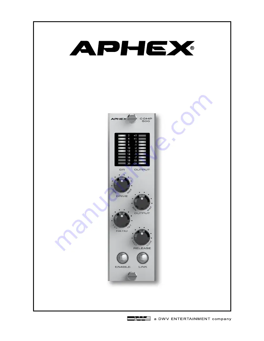
COMP 500

®

OPTICAL COMPRESSOR

500 SERIES MODULE

Summary of Contents for COMP 500

Page 1: ...Owner s Manual COMP 500 OPTICAL COMPRESSOR 500 SERIES MODULE ...

Page 2: ...the equipment into an outlet on a circuit different from that to which the receiver is connected 4 Consult the dealer or an experienced radio TV technician for help CAUTION For continued protection against risk of fire replace only with the same type and rating of fuse ATTENTION pour une protection continue contre les risques d incendie ne remplacer qu avec la même valeur et même type de fusible W...

Page 3: ...00 module into place until it is positively seated in the card slot 5 Use the 2 thumb screws in the module to mount the COMP 500 front panel to the 500 series rack These screws have a pretty tight fit please be careful not to cross thread 6 Plug your 500 series rack back into the AC source and power up your rack Your COMP 500 will automatically power up with your 500 series rack TABLE OF CONTENTS ...

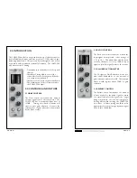
Page 4: ...0 1 This means that with the knob set fully clockwise for every 10dB of input signal only 1dB of signal is sent to the output 3 3 GAIN REDUCTION METER The 10 segment Gain Reduction meter pro vides visual feedback as to the amount of gain reduction measured in dB The example above would register about 12dB of gain reduction 3 4 RELEASE CONTROL The Release control determines the amount of time it ta...

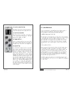
Page 5: ...ack that is too fast can change the natural character of an instrument while too slow can lose the benefits of compression The COMP 500s interactive attack adapts to the input signal controlling volume without changing character and enhancing punch while retaining articulation Typically compression creates more sustain by raising the level as the sound decays This is more or less apparent dependin...

Page 6: ...aced modified or removed c Damage or deterioration 1 Resulting from installation and or removal of the unit 2 Resulting from accident misuse abuse neglect unauthorized product modification or failure to follow instructions contained in the User s Manual 3 Resulting from repair or attempted repair by anyone not authorized by Aphex 4 Occurring from shipping claims must be presented to shipper WHO IS...

Page 7: ...ment and send it to APHEX 3500 N San Fernando Blvd Burbank CA 91505 USA PH 818 767 2929 FAX 818 767 2641 INPUT Type Impedance CMRR Max Input Level comp off Max Input Level comp on OUTPUT Type Impedance Nominal Operating Level Maximum Level Level Meter Peak AUDIO Frequency Response THD THD POWER Current draw OPERATING LEVEL Switch Setting 4dBu Transformerless active balanced 40kohm balanced 20kohm ...

Reviews: