


ACS-2685 User Manual
23
DCIN
ATX12V
AT
(Default)
input
DC9~32V
output
DC 12V
NC
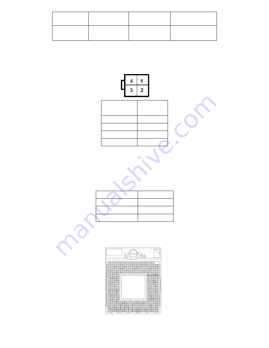
5. ATX12V:
(2x2 Pin Connector),DC12V System power
output
connector.
Pin#
Power
output
Pin1
Ground
Pin2
Ground
Pin3
DC+12V
Pin4
DC+12V
6. ATX
(option)
:
(2.0mm Pitch 1X3 box Pin Header), connect PSON and 5VSB and Ground
signal,support ATX Power model.
Reserved.
Pin#
Signal Name
Pin1
ATX PSON
PIN2
ATX Ground
PIN3
ATX 5VSB
7. CPU1:
(Socket P), installing the CPU Socket.
Summary of Contents for ACS-2685
Page 15: ...ACS 2685 User Manual 15 Figure 1 8 Wall Mount of ACS 2685 with DVD Device Type 2 ...
Page 16: ...ACS 2685 User Manual 16 Figure 1 9 Wall Mount of ACS 2685 with DVD Device Type 3 ...
Page 17: ...ACS 2685 User Manual 17 Figure 1 10 Wall Mount of ACS 2685 Type 4 ...
Page 18: ...ACS 2685 User Manual 18 Figure 1 11 Wall Mount of ACS 2685 Type 5 ...
Page 19: ...ACS 2685 User Manual 19 Chapter 2 Hardware 2 1 Mainboard Figure 2 1 Mainboard Dimensions ...
Page 69: ...ACS 2685 User Manual 69 ...
Page 72: ...ACS 2685 User Manual 72 ...
Page 73: ...ACS 2685 User Manual 73 ...
Page 74: ...ACS 2685 User Manual 74 Click FINISH A Driver Installation Complete ...
Page 76: ...ACS 2685 User Manual 76 ...
Page 77: ...ACS 2685 User Manual 77 Click FINISH A Driver Installation Complete ...
Page 79: ...ACS 2685 User Manual 79 Click FINISH A Driver Installation Complete ...
Page 81: ...ACS 2685 User Manual 81 ...
Page 82: ...ACS 2685 User Manual 82 ...


