AHM-6XX6A User Manual
28
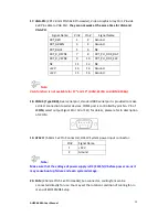
17. VGA-PH:
(CRT 2.0mm Pitch 2x8 Pin Header), Video Graphic Array Port, Provide
2x8 Pin cable to VGA Port,
they can not work at the same time for VGA and
VGA-PH.
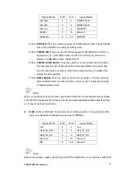
Signal Name
Pin#
Pin#
Signal Name
CRT_RED
1
2
Ground
CRT_GREEN
3
4
Ground
CRT_BLUE
5
6
NC
CRT_R_HSYNC
7
8
CRT_PU_DDC_DAT
CRT_R_VSYNC
9
10
CRT_PU_DDC_CLK
NC
11
12
NC
+12V
13
14
Ground
+12V
15
16
Ground
Note:
VGA function is not available for 17” and 19” (AHM-6176A and AHM-6196A)
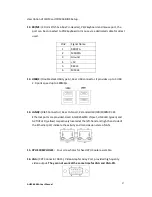
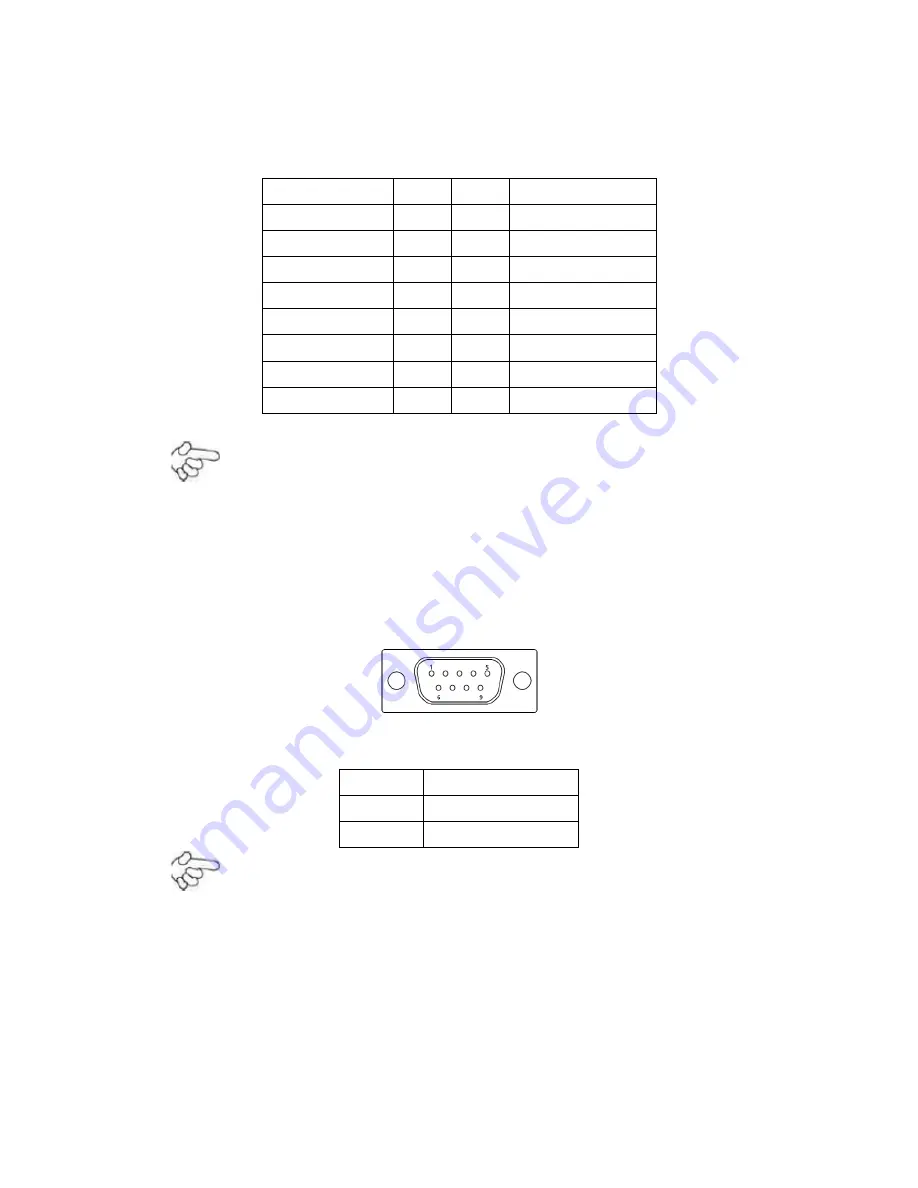
18. COM1: (Type DB9),
Rear serial port, standard DB9 serial port is provided to make
a direct connection to serial devices. COM1 port is controlled by pins No. 1~6 of
JCOM,
select output Signal RI or 5V or 12V, for details, please refer to description
of JCOM.
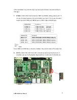
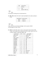
19. AT12V:
(5.0mm 1x2 Pin Connector), DC12V System power input connector.
Pin#
Signal Name
1
+12V
2
Ground
Note:
Make sure that the voltage of power supply is DC (12±5%)V before power on, or it
may cause boot up failure and even system damage.
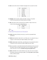
20. FAN:
(2.54mm Pitch 1x3 Pin Header),Fan connector, cooling fans can be
connected directly for use. You may set the rotation condition of cooling fan in
menu of BIOS CMOS Setup.
Summary of Contents for AHM-6XX6A
Page 9: ...AHM 6XX6A User Manual 8 1 2 Dimensions Figure 1 1 Dimensions of the AHM 6086A ...
Page 10: ...AHM 6XX6A User Manual 9 Figure 1 2 Dimensions of the AHM 6126A ...
Page 11: ...AHM 6XX6A User Manual 10 Figure 1 3 Dimensions of the AHM 6156A ...
Page 12: ...AHM 6XX6A User Manual 11 Figure 1 4 Dimensions of the AHM 6176A ...
Page 13: ...AHM 6XX6A User Manual 12 Figure 1 5 Dimensions of the AHM 6196A ...
Page 63: ...AHM 6XX6A User Manual 62 ...
Page 66: ...AHM 6XX6A User Manual 65 ...
Page 67: ...AHM 6XX6A User Manual 66 ...
Page 70: ...AHM 6XX6A User Manual 69 ...
Page 73: ...AHM 6XX6A User Manual 72 Click FINISH A Driver Installation Complete ...
Page 77: ...AHM 6XX6A User Manual 76 5 Installing ...
Page 78: ...AHM 6XX6A User Manual 77 6 The Install Shield Wizard Completed appears Click Finish ...


