APC-3X98(A) User Manual
14
2
Ground
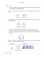
Note:
Make sure that the voltage of power supply is DC9V~30V before power on, or it may cause
boot up failure and even system damage.
3. BAT1:
(1.25mm Pitch 1X2 box Pin Header) 3.0V Li battery is embedded to provide power for
CMOS.
Pin#
Signal Name
Pin1
VBAT
PIN2
Ground
4. USB23/USB45
:
(Double stack USB type A), Rear USB connector, it provides up to 4 USB2.0 ports,
speed up to 480Mb/s.
5. LAN1:
(RJ45
Connector
),
Rear LAN port, 1 standard 10/100/1000M RJ-45 Ethernet ports are
provided. Used Intel 82574L chipset ,LINK LED (green) and ACTIVE LED (yellow) respectively
located at the left-hand and right-hand side of the Ethernet port indicate the activity and transmission
state of LAN.
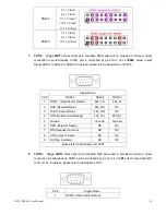
6. JP485:
(2.0mm Pitch 2x9 Pin Header), COM1 setting jumper, pin 1~18 are used to select signal out
of COM1 port of RS232 or RS422 or RS485 mode.
COM1 Mode
JP485 Setting
RS232
(default)
1-3 ( Close)
2-4 ( Close)
7-9 ( Close)
8-10 ( Close)
13-14 (Close)
Summary of Contents for APC-3098
Page 7: ...APC 3X98 A User Manual 7 Certificate CE FCC Class A ...
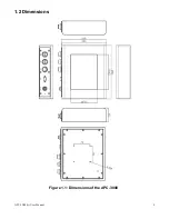
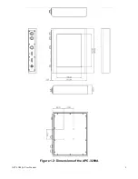
Page 8: ...APC 3X98 A User Manual 8 1 2 Dimensions Figure 1 1 Dimensions of the APC 3098 ...
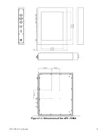
Page 9: ...APC 3X98 A User Manual 9 Figure 1 2 Dimensions of the APC 3298A ...
Page 10: ...APC 3X98 A User Manual 10 Figure 1 3 Dimensions of the APC 3598A ...
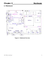
Page 12: ...APC 3X98 A User Manual 12 Chapter 2 Hardware 2 1 Mainboard Figure 2 1 Mainboard Overview ...
Page 48: ...APC 3X98 A User Manual 48 ...
Page 51: ...APC 3X98 A User Manual 51 ...
Page 52: ...APC 3X98 A User Manual 52 Click FINISH A Driver Installation Complete ...
Page 54: ...APC 3X98 A User Manual 54 ...
Page 55: ...APC 3X98 A User Manual 55 Click FINISH A Driver Installation Complete ...
Page 57: ...APC 3X98 A User Manual 57 Click FINISH A Driver Installation Complete ...
Page 61: ...APC 3X98 A User Manual 61 5 Installing ...
Page 62: ...APC 3X98 A User Manual 62 6 The Install Shield Wizard Completed appears Click Finish ...


