APC-3x15 User Manual
38
Chapter 3 BIOS Setup
3.1 BIOS Setup
This chapter describes the different settings available in the Award BIOS that comes
with the board. The topics covered in this chapter are as follows:
BIOS Introduction
BIOS Setup
Standard CMOS Setup
Advanced BIOS Features
Advanced Chipset Features
Integrated Peripherals
Power Management Setup
PNP/PCI Configurations
PC Health Status
Frequency/Voltage Control
Load Fail-Safe Defaults
Load Optimized Defaults
Set Supervisor/User Password
Save & Exit Setup
Exit Without Saving
BIOS Introduction
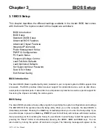
The Award BIOS (Basic Input/Output System) installed in your computer system’s ROM supports Intel
processors. The BIOS provides critical low-level support for standards devices, such as disk drives,
serial ports and parallel ports. It also adds virus and password protection as well as special support for
fine-tuning the chipset controlling the entire system.
BIOS Setup
The Award BIOS provides a Setup utility program for specifying the system configurations and settings.
The BIOS ROM of the system stores the Setup utility. When you on the computer, the Award BIOS is
immediately activated. Pressing the
<Del>
key immediately allows you to enter the Setup utility. If you
are a little bit late to press the
<Del>
key,
POST
(Power On Self Test) will continue with its test routines,
thus preventing you from invoking the Setup. If you still wish to enter Setup, restart the system by the
pressing the “Reset” button or simultaneously pressing the
<Ctrl>
,
<Alt>
and
<Del>
keys. You can
also restart by turning the system off and back on again. The following message will appear on the
Summary of Contents for APC-3215
Page 8: ...APC 3x15 User Manual 8 1 2 Dimensions Figure 1 1 Dimensions of the APC 3215 ...
Page 9: ...APC 3x15 User Manual 9 Figure 1 2 Dimensions of the APC 3515 ...
Page 10: ...APC 3x15 User Manual 10 Figure 1 3 Dimensions of the APC 3715 ...
Page 11: ...APC 3x15 User Manual 11 Figure 1 4 Dimensions of the APC 3915 ...
Page 18: ...APC 3x15 User Manual 18 Chapter 2 Hardware 2 1 Mainboard Figure 2 1 Mainboard Overview ...
Page 22: ...APC 3x15 User Manual 22 ...
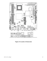
Page 24: ...APC 3x15 User Manual 24 Figure 2 5 Location of Connectors ...
Page 25: ...APC 3x15 User Manual 25 ...
Page 26: ...APC 3x15 User Manual 26 ...
Page 27: ...APC 3x15 User Manual 27 ...
Page 28: ...APC 3x15 User Manual 28 ...
Page 29: ...APC 3x15 User Manual 29 ...
Page 30: ...APC 3x15 User Manual 30 ...
Page 31: ...APC 3x15 User Manual 31 ...
Page 32: ...APC 3x15 User Manual 32 ...
Page 33: ...APC 3x15 User Manual 33 ...
Page 34: ...APC 3x15 User Manual 34 ...
Page 35: ...APC 3x15 User Manual 35 ...
Page 36: ...APC 3x15 User Manual 36 ...
Page 37: ...APC 3x15 User Manual 37 ...
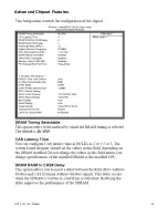
Page 46: ...APC 3x15 User Manual 46 Advanced Chipset Features ...
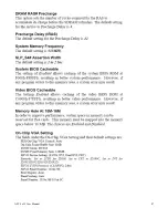
Page 47: ...APC 3x15 User Manual 47 ...
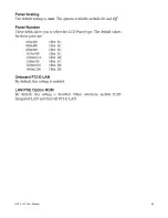
Page 48: ...APC 3x15 User Manual 48 ...
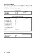
Page 49: ...APC 3x15 User Manual 49 ...
Page 50: ...APC 3x15 User Manual 50 ...
Page 51: ...APC 3x15 User Manual 51 ...
Page 52: ...APC 3x15 User Manual 52 ...
Page 53: ...APC 3x15 User Manual 53 ...
Page 54: ...APC 3x15 User Manual 54 ...
Page 55: ...APC 3x15 User Manual 55 ...
Page 56: ...APC 3x15 User Manual 56 ...
Page 57: ...APC 3x15 User Manual 57 ...
Page 58: ...APC 3x15 User Manual 58 ...
Page 59: ...APC 3x15 User Manual 59 ...
Page 74: ...APC 3x15 User Manual 74 ...

