APC-3296P User Manual
43
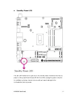
PWR-LED - Power/Standby LED
When the system’s power is on, this LED will light. When the system is in the S1
(POS – Power On Suspend) state, it will blink every second. When the system is in the
S3 (STR - Suspend To RAM) state, it will blink every 4 seconds.
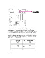
Pin Pin Assignment
Pin Pin Assignment
HDD-LED
3
HDD Power
PWR-LED
2
LED Power
5
Signal
4
LED Power
RESET-SW
7
Ground
6
Signal
9
RST Signal
PWR-BTN
8
Ground
11
N.C.
10
Signal
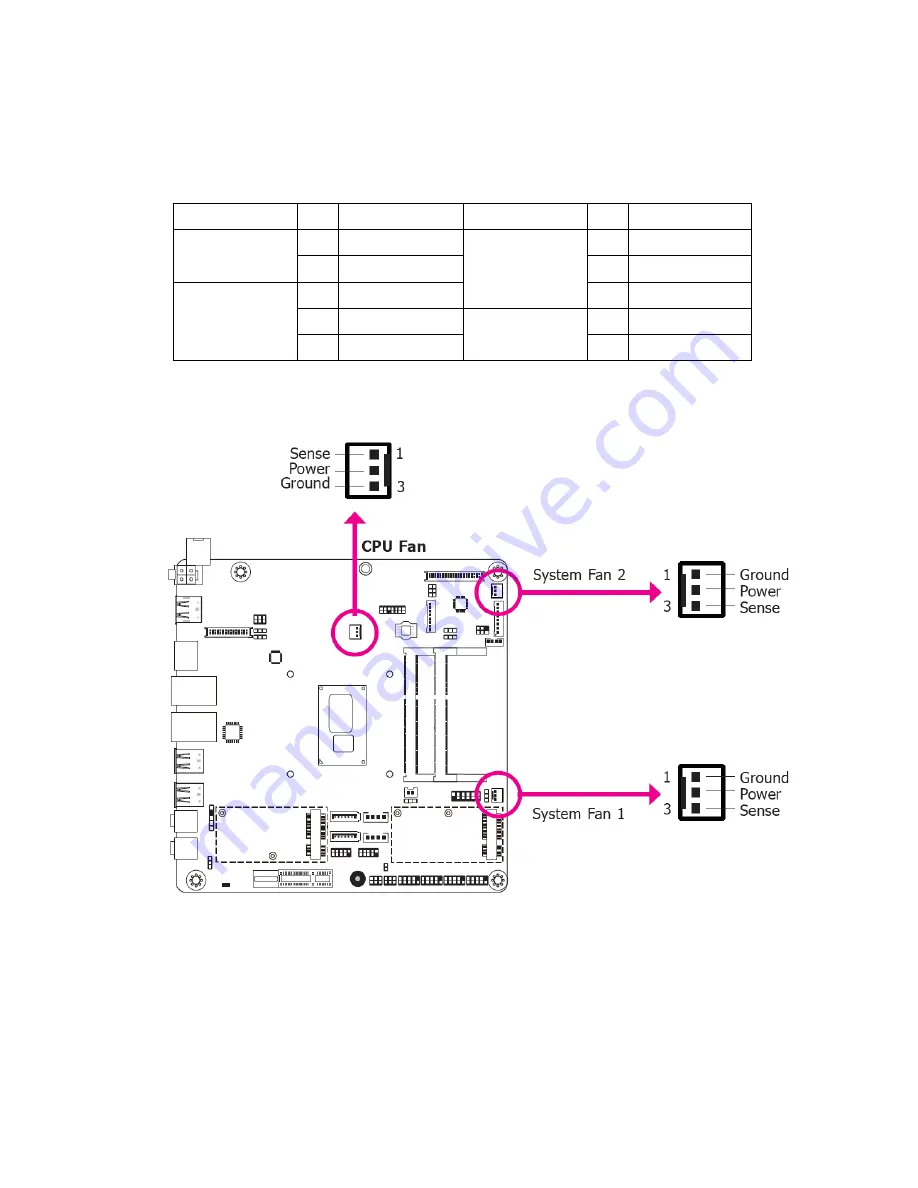
Cooling Fan Connectors
The fan connectors are used to connect cooling fans. The cooling fans will provide
adequate airflow throughout the chassis to prevent overheating the CPU and system
board components.
BIOS Setting
The Advanced menu (“SIO NUVOTON6106D” submenu) of the BIOS will display the
current speed of the cooling fans. Refer to chapter 3 for more information.
Summary of Contents for APC-3296P
Page 10: ...APC 3296P User Manual 9 1 3 Dimensions Figure 1 1 Dimensions of APC 3296P ...
Page 66: ...APC 3296P User Manual 65 ...
Page 75: ...APC 3296P User Manual 74 ...
Page 76: ...APC 3296P User Manual 75 For Windows 8 ...
Page 77: ...APC 3296P User Manual 76 For Windows 7 ...
Page 100: ...APC 3296P User Manual 99 Step 6 Setup is now installing the driver Step 7 Click Finish ...
Page 104: ...APC 3296P User Manual 103 Step 7 Click Finish to complete installation ...

