27
21. JP2:
(2.0mm Pitch 2x3 Pin Header),COM2 jumper setting, pin 1~6 are used to select signal
out of pin 9 of COM2 port.
JP2 Pin#
Function
Close 1-2
COM2 Pin9 RI (Ring Indicator) (default)
Close 3-4
COM2 Pin9=+5V
(option)
Close 5-6
COM2 Pin9=+12V
(option)
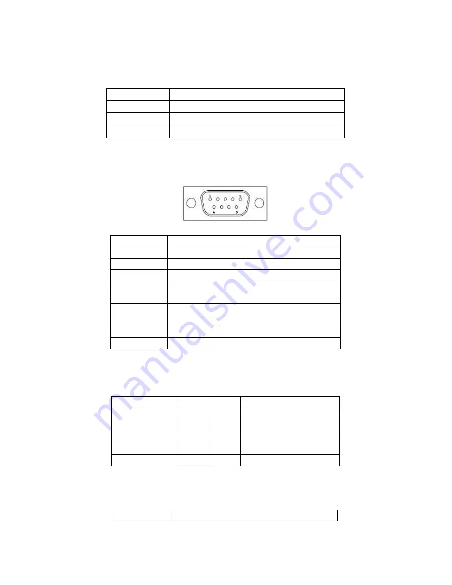
22. COM2:
(Type DB9)
,
Rear serial port, standard DB9 Male serial port is provided to make a direct
connection to serial devices.
Pin#
Signal Name
1
DCD# (Data Carrier Detect)
2
RXD (Received Data)
3
TXD (Transmit Data)
4
DTR (Data Terminal Ready)
5
Ground
6
DSR (Data Set Ready)
7
RTS (Request To Send)
8
CTS (Clear To Send)
9
JP2 select Setting
(RI/5V/12V)
23. COM5
:
(2.0mm Pitch 2X5 Pin Header),COM5 Port, standard RS232 ports are provided. They
can be used directly via COM cable connection.
Signal Name
Pin#
Pin#
Signal Name
DCD
1
2
RXD
TXD
3
4
DTR
Ground
5
6
DSR
RTS
7
8
CTS
RI
9
10
NC
24. JP3:
(2.0mm Pitch 1x3 Pin Header) COM6 setting jumper, pin 1~6 are used to select signal out
of pin 9 of COM6 port.
JP3 Pin#
Function
Summary of Contents for APC-3519
Page 8: ...8 Figure 1 2 Dimensions of APC 3719 ...
Page 9: ...9 Figure 1 3 Dimensions of APC 3919 ...
Page 14: ...14 Step 4 Put the riser card in Put the riser card in Put the riser card in ...
Page 15: ...15 Step 5 Tighten two screws ...
Page 20: ...20 Figure 2 3 Jumpers and Connectors Location Bottom ...
Page 58: ...APC 3X19 User Manual 58 Step 5 Click Next Step 6 Click Next ...
Page 59: ...APC 3X19 User Manual 59 Step 7 Select Yes I want to restart this computer now Click Finish ...
Page 64: ...APC 3X19 User Manual 64 Step 3 Select Yes I want to restart my computer now then click Finish ...
Page 70: ...APC 3X19 User Manual 70 Step 6 Click Finish to compete the setup ...
Page 80: ...APC 3X19 User Manual 80 Setting ...
Page 83: ...APC 3X19 User Manual 83 Step 2 When the mapping screen message appears click OK ...
Page 87: ...APC 3X19 User Manual 87 NOTE The Rotate function is disabled if you use Monitor Mapping ...


