APC-3x84B/APC-3x85B User Manual
24
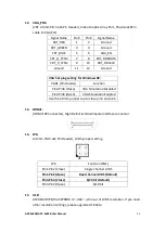
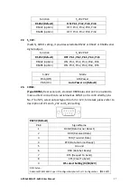
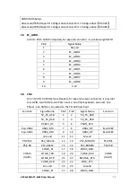
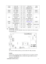
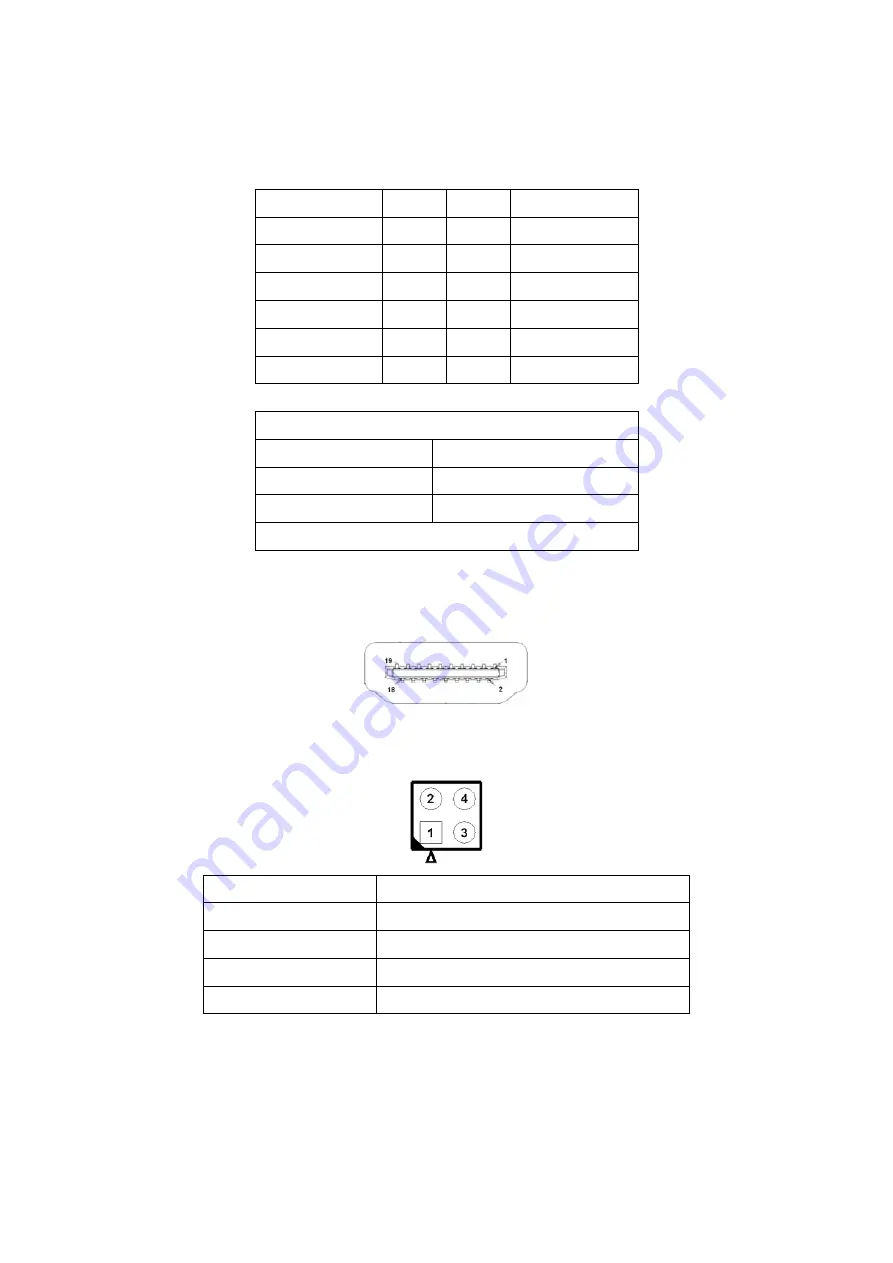
12. VGA_PH1:
(CRT 2.0mm Pitch 2x6 Pin Header), Video Graphic Array Port, Provide 2x6Pin
cable to VGA Port.
Signal Name
Pin#
Pin#
Signal Name
CRT_RED
1
2
Ground
CRT_GREEN
3
4
Ground
CRT_BLUE
5
6
VGA_EN
CRT_H_SYNC
7
8
CRT_DDCDATA
CRT_V_SYNC
9
10
CRT_DDCCLK
Ground
11
12
Ground
VGA hot plug setting for Windows XP:
VGA1 (Pin Header)
Function
Pin4-Pin6 (Close)
VGA Simulation Disabled
Pin4-Pin6 (Open)
VGA Simulation Enabled
Use the 2.0mm jumper cap to close pin4 and pin6
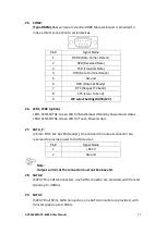
13. HDMI1:
(HDMI 19P Connector), High Definition Multimedia Interface connector.
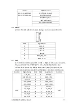
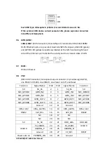
14. JP6:
(2.0mm Pitch 2x2 Pin Header), LVDS jumper setting.
JP6
Function (CN1)
Pin1-Pin2 (Close)
Single channel LVDS
Pin1-Pin2 (Open)
Dual channel LVDS (Default)
Pin3-Pin4 (Close)
8/24 bit (Default)
Pin3-Pin4 (Open)
6/18 bit
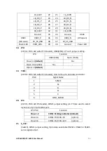
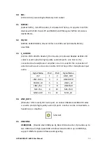
15. U18:
AT24C02-DIP8,The EEPROM IC
(
U18
)
is the set of LVDS resolution. If you need
other resolution settings, please upgrade U18 data.
Summary of Contents for APC-3584B
Page 1: ......
Page 72: ...APC 3x84B APC 3x85B User Manual 70 Step 3 Read license agreement Click Yes Step 4 Click Next ...
Page 73: ...APC 3x84B APC 3x85B User Manual 71 Step 5 Click Install Step 6 Click Install ...
Page 84: ...APC 3x84B APC 3x85B User Manual 82 Step 4 Click Finish to complete the installation ...

