APC-3X19 User Manual
33
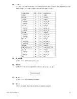
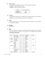
Pin#
Signal Name
1
+DC5V
2
Ground
3
Ground
4
+DC12V
Note:
Output current of the connector must not be above 1A.
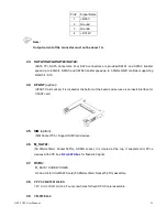
43. SATA1/SATA2/SATA3/SATA4:
(SATA 7P), SATA Connectors, Four SATA connectors are provided,SATA1 and SATA2 transfer
speed up to 6.0Gb/s, SATA3 and SATA4 transfer speed up to 3.0Gb/s,RAID controller supporting
RAID 0/1/5/10.
44. CFAST
(option)
:
(
CFAST Card socket), it is located at the bottom of the board and serves as an insert interface for
CFAST card.
45. SIM
(option)
:
(SIM Socket 7Pin), Support SIM Card devices.
46. M_SATA1:
(50.95mmx30mm Socket 52Pin), mSATA socket, it is located at the top, it supports mini PCI-e
devices with LPC bus,
B2 mSATA bus
for flash disk signal.
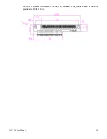
47. H3/H4:
M_SATA1 SCREW HOLES,
H3 and H4 for mini MSATA card (50.95mmx30mm Socket 52 Pin) assemble.
48.
CPU SCREW HOLES:
CPU FAN SCREW HOLES,
Four screw holes for fixed CPU Cooler
assemble.
49.
TB-525E161:
Summary of Contents for APC-3X19
Page 9: ...APC 3X19 User Manual 9 Figure 1 3 Dimensions of APC 3919 ...
Page 13: ...APC 3X19 User Manual 13 Step 5 That s how it should look after it has been installed ...
Page 64: ...APC 3X19 User Manual 64 Step 5 Click Next Step 6 Click Continue Anyway ...
Page 65: ...APC 3X19 User Manual 65 Step 7 Click Continue Anyway Step 8 Click Next ...
Page 66: ...APC 3X19 User Manual 66 Step 9 Select Yes I want to restart this computer now Click Finish ...
Page 70: ...APC 3X19 User Manual 70 Step 6 Click Finish to compete the installation ...
Page 79: ...APC 3X19 User Manual 79 Step 8 Click Finish to compete installation ...
Page 84: ...APC 3X19 User Manual 84 Setting ...
Page 87: ...APC 3X19 User Manual 87 Step 2 When the mapping screen message appears click OK ...
Page 91: ...APC 3X19 User Manual 91 NOTE The Rotate function is disabled if you use Monitor Mapping ...

