APC-3x97B User Manual
19
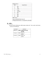
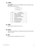
RS485 (option):
Pin#
Signal Name
1
NC
2
NC
3
485-
4
485+
5
Ground
6
NC
7
NC
8
NC
9
NC
BIOS Setup
:
Advanced/W83627UHG Super IO
Configuration/Serial Port 1 Configuration
【
RS-485
】
12 JP2:
(2.0mm Pitch 2x3 Pin Header), COM2 jumper setting, pin 1~6 are used to select signal
out of pin 9 of COM2 port.
JP2 Pin#
Function
Close 1-2 COM1 RI (Ring Indicator)
(default)
Close 3-4
COM1 Pin9=+5V
(option)
Close 5-6
COM1 Pin9=+12V
(option)
Summary of Contents for APC-3x97B
Page 9: ...APC 3x97B User Manual 9 Figure 1 4 Dimensions of APC 3997B ...
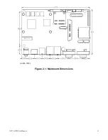
Page 13: ...APC 3x97B User Manual 13 units mm Figure 2 1 Mainboard Dimensions ...
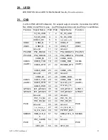
Page 23: ...APC 3x97B User Manual 23 3P3V_S5 57 58 3P3V_S5 12V 12V_S0 59 60 12V_S0 12V ...
Page 54: ...APC 3x97B User Manual 54 Step 3 Read license agreement Click Yes Step 4 Click Next ...
Page 66: ...APC 3x97B User Manual 66 Step 2 Click Standard Calibration to start calibration procedure ...

