background image

FABS-1XXP/G(H) User Manual   

33 

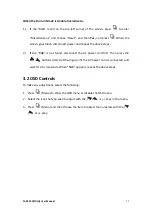
When the Burn-in Mode is Unable to Eradicate… 

1.)


If  the  “RGB”  is  still  on  the  top  left  corner  of  the  screen,  press 

  to  enter 

“Miscellaneous”  and  choose  “Reset”,  and  then

  Yes, 

and  press 

.  When  the 

screen goes black, disconnect power and repeat the above steps. 


2.)


If  the  “RGB”  is  not  found,  disconnect  the  AC  power  cord  first.  Then  press  the 


  buttons (don’t let them go) until the AC power cord is connected, and 

wait for 2 to 3 seconds. When “RGB” appears, repeat the above steps. 


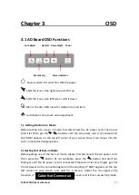
3.2 OSD Controls 

To make any adjustment, select the following: 

1.


Press 

  (Menu) to show the OSD menu or disable the OSD menu. 

2.


Select the icon that you wish to adjust with the (

/

  or +/-) key in the menu. 

3.


Press 

  (Menu) and then choose the item or adjust the numerals with the (

/

  or +/-) key. 


Summary of Contents for FABS-1 Series

Page 1: ...ailable Lifetime Technical Support Our Services Electronic Design Production Management Assembly and Test Bespoke BIOS Creation Industrial Embedded PC Solutions www dsl ltd co uk Email us at sales dsl ltd co uk Call us on 44 0 1462 675330 Electronic Design Panel PC HMI Single Board Computer Industrial PC ...

Page 2: ...tainless Steel Chassis Display User Manual Release Date Revision Aug 2019 V1 0 2019 Aplex Technology Inc All Rights Reserved Published in Taiwan Aplex Technology Inc 15F 1 No 186 Jian Yi Road Zhonghe District New Taipei City 235 Taiwan Tel 886 2 82262881 Fax 886 2 82262883 URL http www aplextec com zh home php ...

Page 3: ...FABS 1XXP G H User Manual 1 Revision History Reversion Date Description 1 0 2019 08 28 Official Version ...

Page 4: ...erated in a commercial environment Operation of this equipment in a residential area is likely to cause interference in which case the user at his own expense will be required to take whatever measures may be required to correct the interference Disclaimer This information in this document is subject to change without notice In no event shall Aplex Technology Inc be liable for damages of any kind ...

Page 5: ...2 3 Jumpers and Connectors Location 22 2 4 Jumper Settings and Connectors 33 Chapter 3 OSD 3 1 AD Board OSD Functions 32 3 2 OSD Controls 33 3 3 Main Menu 34 Appendix A Panel Mounting and VESA Mounting Panel mounting and VESA mounting 37 Figures Figure 1 1 Dimensions of FABS 107PG H 9 Figure 1 2 Dimensions of FABS 110PG H 9 Figure 1 3 Dimensions of FABS 112PG H 10 Figure 1 4 Dimensions of FABS 115...

Page 6: ...Rear View of FABS 112PG H 15 Figure 1 14 Front View of FABS 115PG H 16 Figure 1 15 Rear View of FABS 115PG H 16 Figure 1 16 Front View of FABS 117PG H 17 Figure 1 17 Rear View of FABS 117PG H 17 Figure 1 18 Front View of FABS 119PG H 18 Figure 1 19 Rear View of FABS 119PG H 18 Figure 1 20 Front View of FABS 121PG H 19 Figure 1 21 Rear View of FABS 121PG H 19 Figure 2 1 Dimensions of TB 6802 Top 21...

Page 7: ...ons FABS 1XX Series Outside I O Port VGA 1 DVI D 1 x DVI D input share with HDMI DP 1 HDMI 1 x HDMI input share with DVI D Audio 1 x audio line in phone jack OSD control OSD on the rear side LED Light 1 x system power LED light Speaker 1 x 2W speaker for option Power 1 x 3 pins terminal block for DC 9 36V power input Others 1 x USB type B for touch control 1 x RS 232 DB 9 for touch control for opt...

Page 8: ...eration Certification CE FCC Class A design ready to meet EN1672 2 standard Power Consumption Model Name FABS 107P G H FABS 110P G H FABS 112P G H FABS 115P G H FABS 117P G H FABS 119P G H FABS 121P G H Power Consumption 5 63W STD LCD 9 55W STD LCD 12 48W HB LCD 16 40W HB LCD 29 22W HB LCD Mechanical Specification Model Name FABS 107P G H FABS 110P G H FABS 112P G H FABS 115P G H FABS 117P G H FAB...

Page 9: ...450 500 Viewing Angle H V 110 140 170 170 178 178 160 140 Backlight Lifetime Hrs 40 000 25 000 50 000 30 000 FABS 115P FABS 117P FABS 119P FABS 121P Display Type 15 color TFT LCD 17 color TFT LCD 19 color TFT LCD 21 5 color TFT LCD Max Resolution 1024 x 768 1280 x 1024 1280 x 1024 1920 x 1080 Max Colors 16 2M 16 7M 16 7M 16 7M Contrast Ratio 2000 1 800 1 1000 1 3000 1 Luminance cd m 2 300 350 350 ...

Page 10: ... 1000 1000 1000 Viewing Angle H V 130 140 170 170 178 178 160 140 Backlight Lifetime Hrs 50 000 50 000 50 000 50 000 FABS 115PH FABS 117PH FABS 119PH FABS 121PH Display Type 15 color TFT LCD 17 color TFT LCD 19 color TFT LCD 21 5 color TFT LCD Max Resolution 1024 x 768 1280 x 1024 1280 x 1024 1920 x 1080 Max Colors 16 7M 16 7M 16 7M 16 7M Contrast Ratio 800 1 1000 1 1000 1 3000 1 Luminance cd m 2 ...

Page 11: ...FABS 1XXP G H User Manual 9 1 3 Dimensions Figure 1 1 Dimensions of FABS 107PG H Figure 1 2 Dimensions of FABS 110PG H ...

Page 12: ...FABS 1XXP G H User Manual 10 Figure 1 3 Dimensions of FABS 112PG H Figure 1 4 Dimensions of FABS 115PG H ...

Page 13: ...FABS 1XXP G H User Manual 11 Figure 1 5 Dimensions of FABS 117PG H Figure 1 6 Dimensions of FABS 119PG H ...

Page 14: ...chassis display which comes with 7 to 21 5 color TFT LCD The optional high brightness LCD is ideal for sunlight readable semi outdoor applications Furthermore 12 1 display can be XGA 1024 x 768 resolution for option The model series supports VGA DP and DVI D HDMI input and it can be VESA 100 x 100 mounted FABS 1XXPG H series have more outstanding features and the best performance in monitoring ...

Page 15: ...FABS 1XXP G H User Manual 13 Figure 1 8 Front View of FABS 107PG H Figure 1 9 Rear View of FABS 107PG H ...

Page 16: ...FABS 1XXP G H User Manual 14 Figure 1 10 Front View of FABS 110PG H Figure 1 11 Rear View of FABS 110PG H ...

Page 17: ...FABS 1XXP G H User Manual 15 Figure 1 12 Front View of FABS 112PG H Figure 1 13 Rear View of FABS 112PG H ...

Page 18: ...FABS 1XXP G H User Manual 16 Figure 1 14 Front View of FABS 115PG H Figure 1 15 Rear View of FABS 115PG H ...

Page 19: ...FABS 1XXP G H User Manual 17 Figure 1 16 Front View of FABS 117PG H Figure 1 17 Rear View of FABS 117PG H ...

Page 20: ...FABS 1XXP G H User Manual 18 Figure 1 18 Front View of FABS 119PG H Figure 1 19 Rear View of FABS 119PG H ...

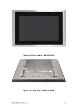
Page 21: ...FABS 1XXP G H User Manual 19 Figure 1 20 Front View of FABS 121PG H Figure 1 21 Rear View of FABS 121PG H ...

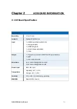
Page 22: ...th DVI D 1 x DisplayPort DP 1 x USB2 0 Type B 1 x DVI D Share with HDMI 1 x VGA Output 1 x Supports up to 24 bit LVDS FULL HD panel interface 1 x eDP 1 x Line out Audio Jack Resolution Up to 1920 x1080 60Hz for LVDS Up to 1920 x1080 60Hz for eDP Power input DC9 36V input Temperature Operating 20 to 70 Storage 40 to 85 Humidity 10 90 non condensing operating EMI EMS Meet CE FCC class A ...

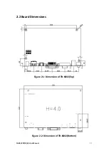
Page 23: ...FABS 1XXP G H User Manual 21 2 2 Board Dimensions Figure 2 1 Dimension of TB 6802 Top Figure 2 2 Dimension of TB 6802 Bottom ...

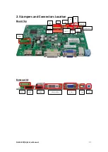
Page 24: ...FABS 1XXP G H User Manual 22 2 3 Jumpers and Connectors Location Board Top External I O JP1 J2 CN8 JP2 JP8 JP3 J4 JP4 NC CN3 PW1 CN4 INVT1 J3 CN7 SPKR1 SKPL1 PW2 DPI HDMI CN1 DVI D VGA1 CN5 CN6 ...

Page 25: ... 2EHDVM 03P TB 6802P ELK508S 03P 2 PW2 Option DC Jack 3 HDMI1 HDMI Input HDMI Connector High Definition Multimedia Interface connector provide high quality video and audio input Signal Name Pin Pin Signal Name DATA2 1 2 DATA2 Shield DATA2 3 4 DATA1 DATA1 Shield 5 6 DATA1 DATA0 7 8 DATA0 Shield DATA0 9 10 CLK HDMI CAB DET 11 12 CLK NC 13 14 NC HDMI SCL 15 16 HDMI SDA GND 17 18 HDMI 5V HDMI HPD 19 ...

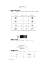
Page 26: ...E3 1 2 GND LANE3 3 4 LANE2 GND 5 6 LANE2 LANE1 7 8 GND LANE1 9 10 LANE0 GND 11 12 LANE0 GND 13 14 GND AUX_CHP 15 16 DP CAB DET AUX_CHN 17 18 DP HPD RETURN 19 20 DP 3 3V 5 CN1 DVI D Iutput DVI D Connector Digital Visual Interface Integrated input connector 6 VGA1 VGA Input CRT DB15 Connector Video Graphic Array Port provide high quality video input Pin Signal Name 1 CRT_RED 2 CRT_GREEN ...

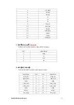
Page 27: ...Reserved 2 0mm 1x4 Pin wafer connector Reserved for IR receiver Pin Signal Name 1 GND 2 IR 3 3 3V 4 NC 8 CN3 eDP Output 1 25mm Pitch 2x15 Connector eDP output connector Signal Name Pin Pin Signal Name LVDS_12V 1 2 LVDS_12V BKLT_CTRL 3 4 BKLT_EN GND 5 6 GND LVDS_VCC5 7 8 LVDS_VCC5 LVDS_VCC3 9 10 LVDS_VCC3 GND 11 12 GND TXA3N 13 14 TXA3P VTX_TX1N 15 16 VTX_TX1P ...

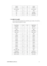
Page 28: ...dual channel 18 24 bit output Signal Name Pin Pin Signal Name LVDS_12V 1 2 LVDS_12V BKLT_CTRL 3 4 BKLT_EN GND 5 6 GND LVDS_VCC5 7 8 LVDS_VCC5 LVDS_VCC3 9 10 LVDS_VCC3 GND 11 12 GND TXA0N 13 14 TXA0P TXA1N 15 16 TXA1P TXA2N 17 18 TXA2P TXA3N 19 20 TXA3P TXACN 21 22 TXACP TXB0N 23 24 TXB0P TXB1N 25 26 TXB1P TXB2N 27 28 TXB2P TXBCN 29 30 TXB3P TXB3N 31 32 TXBCP LVDS_DDC_DET 33 34 GND CPT USB_N 35 36 ...

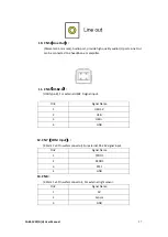
Page 29: ...eadphone or amplifier 11 CN6 USB2 0 USB Type B For external USB2 0 signal input Pin Signal Name 1 USB 5V 2 USB 3 USB 4 GND 12 CN7 COM Input 2 0mm 1x4 Pin wafer connector For external RS 232 signal input Pin Signal Name 1 TXDD1 2 RXDD1 3 RTS1 4 GND 13 CN8 2 0mm 1x3 Pin wafer connector For external light sensor Pin Signal Name 1 5V 2 Sensor 3 GND ...

Page 30: ...5 BKLT_EN 6 BKLT_CTRL 15 JP1 OSD 2 0mm 1x9 Pin wafer connector On Screen Display menu Control connector Pin Signal Name 1 Power Key 2 R_LED 3 G_LED 4 GND 5 MENU Key 6 Down Key 7 UP Key 8 Select Key 9 NC 16 JP2 2 0mm Pitch 1x3 Pin Header JP2 Pin Function Close 1 2 Backlight Enable Backlight PWM Level select 3 3V Close 2 3 Backlight Enable Backlight PWM Level select 5V ...

Page 31: ...in Header Pin Signal Name 1 NC 2 VCC3 3 NC 4 TICEDAT 5 NC 6 TICECLK 7 UART0_TX 8 nRST 9 UART0_RX 10 GND 19 JP8 2 0mm Pitch 1x3 Pin Header JP8 Pin Function Close 1 2 Backlight Control Backlight PWM Level select 3 3V Close 2 3 Backlight Control Backlight PWM Level select 5V 20 J1 VGA input 2 0mm Pitch 1X12 Pin Wafer Video Graphic Array Port Provide 12Pin cable to VGA output Pin Signal Name 1 GND 2 V...

Page 32: ...ontroller Signal jumper setting J2 PM6000 input Signal CN4 USB output Close 3 5 4 6 NC Close 1 3 2 4 USB CN6 NC Close 1 3 2 4 RS232 CN7 NC Close 1 3 2 4 RS232 CN7 NC 22 J3 2 0mm Pitch 1X6 Pin Wafer Touch Screen connecting Lines Pin 4 Wire 5 Wire 1 N A Sense S 2 Right LR 3 Left LL 4 Bottom UR 5 Top UL 6 GND GND 23 J4 Reserved 2 0mm Pitch 1x2 Pin Header 4 Wire 8 Wire resistive touch select ...

Page 33: ...KL1 Audio output 2 0mm 1x2 Pin wafer connector Amplifier left channel output Pin Signal Name 1 L output 2 L output 25 SPKR1 Audio output 2 0mm 1x2 Pin wafer connector Amplifier right channel output Pin Signal Name 1 R output 2 R output ...

Page 34: ... t let them go the buttons until the AC power cord is connected and the RGB appears on the top left corner of your screen Now it can be put into the burn in mode for changing colors 2 Getting Out of Burn in Mode Before getting out of the burn in mode please first disconnect the AC power cord Then press the button If not workable press the button and don t let them go until the AC power cord is con...

Page 35: ... 2 If the RGB is not found disconnect the AC power cord first Then press the buttons don t let them go until the AC power cord is connected and wait for 2 to 3 seconds When RGB appears repeat the above steps 3 2 OSD Controls To make any adjustment select the following 1 Press Menu to show the OSD menu or disable the OSD menu 2 Select the icon that you wish to adjust with the or key in the menu 3 P...

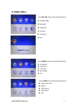
Page 36: ...the following items AutoBacklight Backlight Brightness Contrast Sharpness Exit In the DISPLAY there are the following items AutoAdjust H Position V Position Disp Rotate Exit In the COLOR there are the following items Panel Uniformity Gamma Temperature Color Effect Exit ...

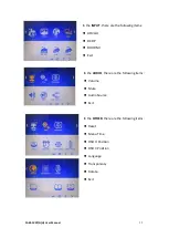
Page 37: ...e are the following items A0 VGA D1 DP D3 HDMI Exit In the AUDIO there are the following items Volume Mute Audio Source Exit In the OTHER there are the following items Reset Menu Time OSD H Position OSD V Position Language Transparency Rotate Exit ...

Page 38: ...FABS 1XXP G H User Manual 36 Information part ...

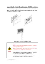
Page 39: ...SA mounting Notice Tighten the mounting clip screws by hand until the gasket seal contacts the mounting surface uniformly Tighten the mounting clips screws to a torque of 8 10 kgf cm by using the specified sequence making sure not to overtighten Tighten the mounting clips to the specified torque to provide a proper seal and to prevent damage to the product Aplex assumes no responsibility for water...

Reviews: