


NV-266XC User Manual
19
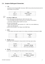
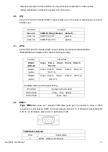
2.4 Jumpers Setting and Connectors
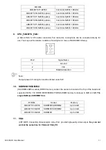
1. JP1:
(2.0mm Pitch 1X3 Pin Header)CMOS clear jumper, CMOS clear operation will permanently reset old
BIOS settings to factory defaults.
JP1
CMOS
Close 1-2
NORMAL (Default)
Close 2-3
Clear CMOS
Procedures of CMOS clear:
a) Turn off the system and unplug the power cord from the power outlet.
b) To clear the CMOS settings, use the jumper cap to close pins2 and 3 for about 3
seconds then reinstall the jumper clip back to pins open.
c) Power on the system again.
d) When entering the POST screen, press the <F1> or <DEL> key to enter CMOS Setup
Utility to load optimal defaults.
e) After the above operations, save changes and exit BIOS Setup.
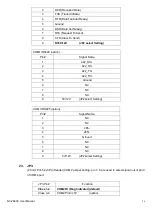
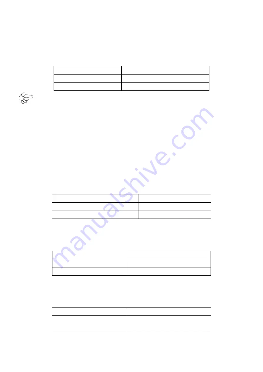
2. BAT1:
(1.25mm Pitch 1X2 Pin wafer connector) 3.0V Li battery is embedded to provide power for CMOS.
Pin#
Signal Name
Pin1
VBAT
PIN2
Ground
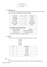
3. PS_SEL1
(option)
:
(2.0mm Pitch 1X3 Pin Header),DC in Power and ATX 12V IN Power jumper setting
.
PS_SEL1
Mode
Close 1-2
DC IN Power (Default)
Close 2-3
ATX 12V_IN (ATX Power)
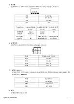
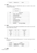
4. PS_ON:
(2.0mm Pitch 1X3 Pin Header),ATX Power and Auto Power on jumper setting
.
JP2
Mode (DC_IN)
Close 1-2
Auto Power on (Default)
Close 2-3 or Open 1-2
ATX Power
Summary of Contents for NV-266 C Series
Page 7: ...NV 266XC User Manual 7 Figure 1 1 Dimensions of NV 2663C ...
Page 8: ...NV 266XC User Manual 8 Figure 1 2 Dimensions of NV 2664C ...
Page 9: ...NV 266XC User Manual 9 Figure 1 3 Dimensions of NV 2665C ...
Page 12: ...NV 266XC User Manual 12 Figure 1 9 Rear view of NV 2665C ...
Page 16: ...NV 266XC User Manual 16 2 2 Board Dimensions ...
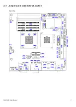
Page 17: ...NV 266XC User Manual 17 2 3 Jumpers and Connectors Location Board Top ...
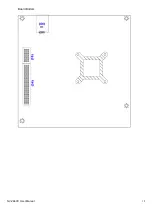
Page 18: ...NV 266XC User Manual 18 Board Bottom ...
Page 66: ...NV 266XC User Manual 66 Step 3 Click I agree Step 4 Click Continue Anyway ...
Page 67: ...NV 266XC User Manual 67 Step 5 Click Continue Anyway Step 6 Click Yes to restart the computer ...


