


NV-266XC User Manual
28
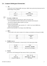
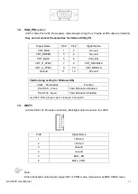
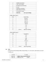
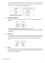
(2.0mm Pitch 2X5 Pin Header), COM6 Port, standard RS232 ports are provided. They can be used
directly via COM cable connection. COM6 port is controlled by pins No.1~6 of JP4,select output
Signal 5V or 12v, For details, please refer to description of
JP4
.
Signal Name
Pin#
Pin#
Signal Name
DCD
1
2
RXD
TXD
3
4
DTR
Ground
5
6
DSR
RTS
7
8
CTS
RI/5V/12V (JP4 select Setting)
9
10
NC
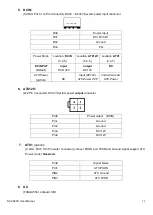
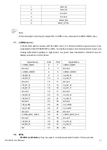
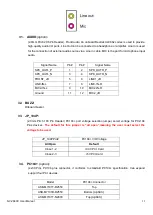
28. USB4/USB5/USB6/USB7
:
(Double stack USB type A), Rear USB connector, it provides up to 4 USB2.0 ports, speed up to
480Mb/s.
Each USB Type A Receptacle (2 Ports) Current limited value is 1.5A.
If the external USB device current exceeds 1.5A, please separate connectors into different
Receptacle.
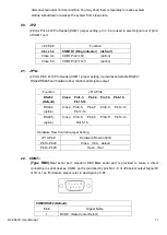
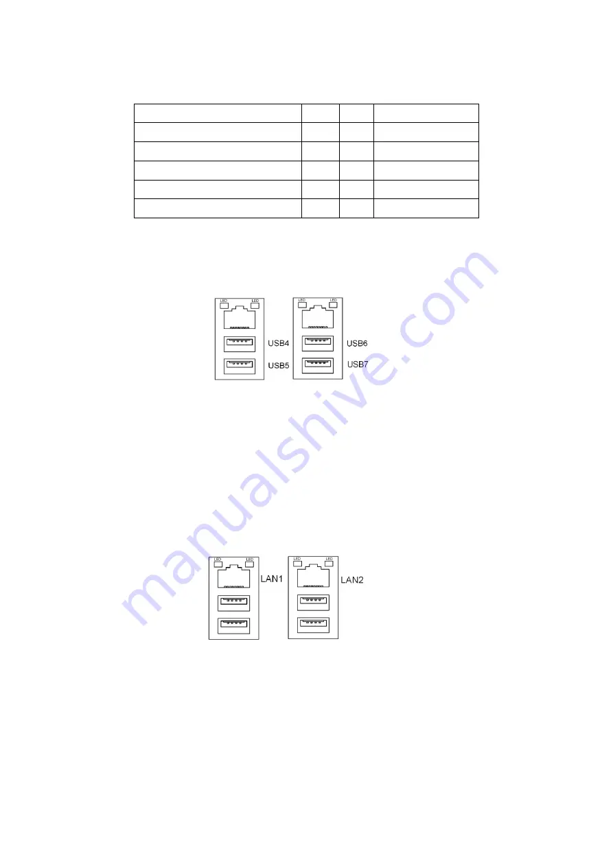
29. LAN1/LAN2:
(RJ45
Connector
),
Rear LAN port, Two standard 10/100/1000M RJ-45 Ethernet ports are provided.
Used Intel 82583V chipset, LINK LED (green) and ACTIVE LED (yellow) respectively located at the
left-hand and right-hand side of the Ethernet port indicate the activity and transmission state of
LAN.
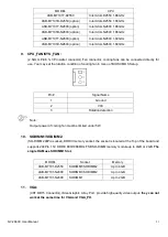
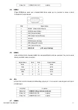
30. JACK
:
(Diameter
3.5mm Double stack Jack), HD Audio port, An onboard Realtek ALC662 codec is used to
provide high quality audio I/O ports. Line Out can be connected to a headphone or amplifier, MIC is
the port for microphone input audio.
Summary of Contents for NV-266 C Series
Page 7: ...NV 266XC User Manual 7 Figure 1 1 Dimensions of NV 2663C ...
Page 8: ...NV 266XC User Manual 8 Figure 1 2 Dimensions of NV 2664C ...
Page 9: ...NV 266XC User Manual 9 Figure 1 3 Dimensions of NV 2665C ...
Page 12: ...NV 266XC User Manual 12 Figure 1 9 Rear view of NV 2665C ...
Page 16: ...NV 266XC User Manual 16 2 2 Board Dimensions ...
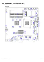
Page 17: ...NV 266XC User Manual 17 2 3 Jumpers and Connectors Location Board Top ...
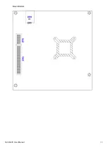
Page 18: ...NV 266XC User Manual 18 Board Bottom ...
Page 66: ...NV 266XC User Manual 66 Step 3 Click I agree Step 4 Click Continue Anyway ...
Page 67: ...NV 266XC User Manual 67 Step 5 Click Continue Anyway Step 6 Click Yes to restart the computer ...