background image


Electrical Installation 


  Read warnings chapter on page 9 on this document.  

  Protect power supply lines (8...32Vdc) with 3A fuse at power supply end of line.  

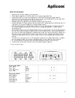
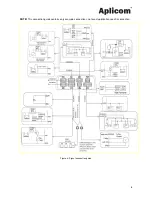
  Connect the cables to A11 device and peripherals as advised in the connection guide. Figure 8.  

  Install the A11 unit as far away as possible (minimum 1 metres recommended) from the car radio and its 

antenna or other electrical devices to avoid any interference. 

  Additional information: Application note

 K505002 Cabling of Aplicom Products

  Avoid ground loops! It is highly recommended to connect all A11 and peripherals ground connections to a 

single point. It is also recommended to use non-grounding antennas. 

  Disconnecting ground lines shall not be done while the unit is connected to power supply of the vehicle. 

This will cause voltage leak between IO connections causing possible problems in external devices 
connected to them. 

  External GPS antenna: Install the GPS/GLONASS antenna to a place where it has the best possible open 

sky view. Please note that Aplicom supplied antennas are installed inside the vehicle, on dashboard, on 
any surface, or windshield, depending on selected antenna type. The antennas direction to satellites must 
be correct to have a good visibility of satellites. Only antennas that are separately specified and clearly 
stated to be used outside of vehicle, can be installed so. Please refer to Aplicom documentation of the 
antenna. 

  If the IGN -line is used ensure that it is connected with suitable fuse to suitable stable source. In modern 

cars for example the lights etc. are pulse controlled and they are not suitable source for IGN –line. 

  A11 unit with CAN bus functionality * do not include internal bus terminator resistors (120

). 

  If wakeup is based on motion then IGN must be connected to power supply line.  


*  CAN bus is available as option. 


 . 


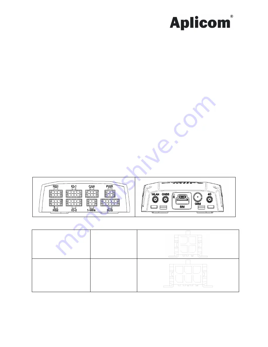
Power cable / PWR 

Pin 1, PWR 
Pin 2, IGN 
Pin 3, PWR OUT 
Pin 4, GND 


Red 
Green 
White 
Black 


Data cable / RS 1/2 

Pin 1,TXD1/3 
Pin2, RXD1/3 
Pin3, GND 
Pin4, TXD 2/4 
Pin5, RXD 2/4 
Pin6, GND


Semo- 
flex  
3x0,25 mm² 
Orange 
Red 
Black


 3 

 5 

 6 

Summary of Contents for A11

Page 1: ...der code K530001 Important Please read this installation guide before the installation Aplicom Oy P O Box 33 FI 44101 Äänekoski Finland Telephone 358 10 841 9414 Fax 358 14 520 800 Business ID 0995791 7 Äänekoski Info aplicom fi www aplicom com ...

Page 2: ...Therefore we reserve the right to make changes and improvements to any of the products described in this guide without prior notice Due to these improvements the contents of this manual are subject to change without notice Aplicom Oy is not responsible for any loss of data income or any consequential damage This crossed out wheelie bin means that within the European Union the product must be taken...

Page 3: ...The following steps must be made in right order to start the unit immediately for full operation 1 Install microSIM card see figure 2 2 Connect external power cabling and other needed connections 3 Mechanically install the unit to carefully selected place 4 Connect the vehicle power supply to A11 wiring power supply with fuse protection Note The internal battery is taken to use when microSIM card ...

Page 4: ...t as far away as possible minimum 1 metres recommended from the car radio and its antenna or other electrical devices to avoid any interference Note If the ACC Acceleration sensor related functions are used make sure that mechanical installation is proper Otherwise ACC results are not reliable Note To ensure the best ACC performance use screws to install the A11 unit Note If the unit is installed ...

Page 5: ...to the surface on which the unit shall be fixed Use the fastener which is delivered in the package Figure 6 There are four mounting lugs on the sides of the A11 device cover Install the A11 device using these mounting lugs with the cable tie Put the cable tie through the openings Maximum width of the cable tie is 4 8mm Use good quality cable ties for example UV Resistant if sun is an issue Figure ...

Page 6: ...LONASS antenna to a place where it has the best possible open sky view Please note that Aplicom supplied antennas are installed inside the vehicle on dashboard on any surface or windshield depending on selected antenna type The antennas direction to satellites must be correct to have a good visibility of satellites Only antennas that are separately specified and clearly stated to be used outside o...

Page 7: ...D indicators Led s A to D are under application SW control led E shows modem and power status and led F shows internal battery charger status Led E Green Unit is powered Flashing orange with 50 50 ratio modem is trying to connect network Green with fast blinks modem is connected to network Led F Orange internal battery not connected failure over temp under temp over time Red internal battery is ch...

Page 8: ...8 NOTE This connection guide contains only example connections not exact application specific connection Figure 8 Signal connection guide ...

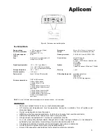
Page 9: ...fit 4 pin for 1 Wire 2 x Molex Microfit 6 pin for serial connection 1 x Molex Microfit 6 pin for CAN 2 x Molex Microfit 8 pin for IO 1 x Molex Microfit 10 pin for K line RS485 Serial and power out connection Note 1 Ensure SIM cards operating temperature range from telecom service provider WARNINGS Warranty is voided if unit or its case is mechanically damaged A11 device and all peripherals must be...

Page 10: ...to car radio or other vehicle systems External antenna cables are led carefully along a well protected route to the device Check that vehicle windows do not have heating system that may block the GPS GLONASS signals for example in dashboard or windshield installations Check the antenna right orientation towards the GPS GLONASS satellites and correct fixing place and surface Power on device Connect...

Reviews: