6
•
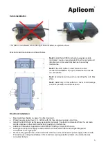
Install the A9 IPEX unit to a place where unit’s internal antennas have the best possible sky view for
GPS/GLONASS satellites and the best possible visibility to GSM/GPRS/3G network base stations.
•
If the IGN
–line is used ensure that it is connected to power line, in modern cars for example the lights
etc. are pulse controlled.
•
A9 IPEX unit
with CAN bus functionality * do not include internal bus terminator resistor (120Ω).
* CAN bus is available as option.
Connection
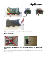
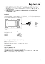
A9 IPEX unit includes an internal terminal block
connector (Figure 8). Wires inside the device cable are
numbered and wire nr 1 is connected to screw connector position 1 as default and wire 2 is connected to
position 2 and so on. The used cable has seven wires.
Figure 8
1 GND
2 PWR
3 IGN/DIN1
4 DIN2
5 OC
6 CANH
7 CANL
Used to SW configuration, COM1 port (sw option) and SW debug.
Note! Use only Aplicom specific cable.
Note! When using this cable, the unit has to be open (top cover removed).
Testing installation
If the unit has a default configuration
1. Connect the power on.
2. Status led is red when the software is started (this takes about 30s).
3. Status led is green when GPS fix is received (this takes about another 30s). Now the unit is working correctly.
Note!
The led is visible only when the unit`s top cover is removed.
Serial data connector
Pin 1, TXD
Pin 2, RXD
Pin 3, GND
1
2
3
4
5
6
7


