background image

1. Safety Instructions 


1.1 Installation


Condensation may occur if the UPS system is moved directly from a cold to 

a  warm  environment.  The  UPS  system  must  be  absolutely  dry  before  being 

installed. Please allow an acclimatization time of at least two hours. 


Do not install the UPS system near water or in damp environments. 


Do not install the UPS system where it would be exposed to direct sunlight 

or near heat. 


Do not connect appliances or items of equipment which would overload the 

UPS system (e.g. laser printers) to the UPS output terminals or sockets. 


Place cables in such a way that no one can step on or trip over them. 


Assure to connect with the earth reliably. 


Connect the UPS only to a socket outlet which is earthed shockproof type. 


The building wiring socket outlet (shockproof socket outlet) must be easily 

accessible to close to the UPS. 


With the installation of the equipment, the sum of the leakage current of the 

UPS and the connected load does not exceed 3.5mA. 


Do  not  block  ventilation  openings  on  the  UPS’s  housing.  Ensure  the  air 

vents on the front, side and rear of the UPS are not blocked. Recommended at 

least 25cm of space on each side. 


This UPS receives power from more than one source-disconnection of AC 

source and the DC source is required to de-energize this unit before servicing.


An additional circuit breaker or fuse with rating 15A and breaking capacity 

3kA shall be used between power source and input when installation this unit. 


1.2 Operation


For safety consideration, do not disconnect the mains cable on the UPS or 

the building wiring socket (grounded shockproof socket) during operation the 

grounding for the UPS and all loads connected will be disconnected. 


The UPS features its own, internal current source (batteries). You may be 

electric shocked when you touch the UPS output sockets or output terminal 

block even if the UPS is not connected to the building wiring socket. 


In order to fully disconnect the UPS, first press the OFF button to turn off 

the UPS, and then disconnect the mains lead. 


  Ensure that no liquid or other external objects can enter the UPS. 


  Do not remove the enclosure. This system is to be serviced by qualified 

service person only. There are NO USER SERVICEABLE PARTS inside the 

UPS. 


Remove the protective panel only after disconnecting the terminal 

connections. 

1.3 Maintenance, Servicing and Fault


The UPS operates with hazardous voltages. Repairs may be carried out 

only by qualified maintenance/service person. 


Caution - risk of electric shock. Even after the unit is disconnected from the 

mains power supply (building wiring socket), components inside the UPS are still 

connected to the battery which are potentially dangerous. 


Before carrying out any kind of service and/or maintenance, disconnect the 

batteries. Verify that no current is present and no hazardous voltage exists in the 

capacitor or BUS capacitor terminals. 


Batteries must be replaced only by qualified person. 

Caution - risk of electric shock. The battery circuit is not isolated from the 

Please  read  the  following  content  and  safety  instructions  before  installation 

or operation. 


27 


Summary of Contents for 208VAC

Page 1: ......

Page 2: ...on 8 4 4 Battery Recharge 9 4 5 Turn ON The UPS 9 4 6 Test Function 9 4 7 Turn OFF The UPS 10 4 8 Audible Alarm Mute Function 10 5 Mode Description 11 6 Setting by LCD Module 17 7 Typical Trouble Shooting 21 8 Maintenance 24 8 1 Operation 24 8 2 Storage 24 9 Product Specification 25 9 1 Electrical Specification 25 9 2 Environment Specification 26 10 Communication Port 26 10 1 USB Interface 26 11 M...

Page 3: ...this unit 1 2 Operation For safety consideration do not disconnect the mains cable on the UPS or the building wiring socket grounded shockproof socket during operation the grounding for the UPS and all loads connected will be disconnected The UPS features its own internal current source batteries You may be electric shocked when you touch the UPS output sockets or output terminal block even if the...

Page 4: ...he same quantity and the same type of batteries Do not attempt to dispose of batteries by burning them It could cause explosion Do not open or destroy batteries Effluent electrolyte can cause injury to the skin and eyes it may be toxic Please replace the fuse only by a fuse of the same type and of the same amperage on order to avoid fire hazards Do not dismantle the UPS except the qualified mainte...

Page 5: ...r batteries the charger will charge the batteries when the mains is in a reasonable range on bypass mode or line mode 3 2 Front Panel LCD Display Button Information Switch Function ON MUTE Button 1 Turn on UPS system By pressing this Button the UPS system is turned on 2 Deactivate acoustic alarm By pressing this Button an acoustic alarm can be deactivated in the battery mode 3 Do the battery test ...

Page 6: ...lso called RPO Remote Power Off Turn off the EPO switch could occur RPO It is a special status in which the UPS would shut the output off and alarm The UPS could not be turned off by pressing OFF Button on the panel only after releasing EPO status by connecting the EPO switch Normally the EPO connector is closed with a wire on the rear panel Once the connector is open Input information Output info...

Page 7: ...UPS could also implement this test automatically and periodically the period time is configurable 4 7 Turn OFF The UPS 1 In Line Mode Press OFF Button continuously for more than 1 second to turn off the UPS the UPS will get into no output or bypass mode In circumstance the UPS might have output power if bypass mode is enabled Disconnect the mains power to turn off the output 2 In Battery Mode Pres...

Page 8: ...ely In this case the normal operating mode string and the warning string will be shown circularly Once a fault comes forth all previous warnings will not be shown again only the fault string will be presented Operating Mode Code Table Warning Code Site fail SITE Fan fail FANF Battery over voltage over charged HIGH Battery low bLOW Charge fail CHGF Inverter temperature high TEPH Battery open bOPN O...

Page 9: ...fied converted by the AC DC section and then inverted to stable output by DC AC section In line mode the output is clean and good to the loads If the mains get abnormal the UPS will transfer to battery mode without interrupt The LCD display in Line mode is shown in the following diagram The information about the utility power the battery level the UPS output and the load level could be displayed T...

Page 10: ...gested to take account of applications for some sensitive load EPO Emergency Power Off It is also called RPO Remote Power Off Turn off the EPO switch could occur RPO On LCD display the mode string is EPO It is a special status in which the UPS would shut the output off and alarm The UPS could not be turned off by pressing OFF Button on the panel only after releasing EPO status by connecting the EP...

Page 11: ... If no any pressing on the SELECT Button or ENTER Button lasting for more than 10 seconds the setting mode will exit automatically The output frequency string OPF Bypass status string bYPA operating mode string MOdE battery remaining time string bATT Charger current string CHG would be presented circularly The only one voltage value can be selected in 220V 230V 240V at any time The only one freque...

Page 12: ...2 OPF after pressing the SELECT Button Step 3 bYPA after pressing the SELECT Button Step 4 MOdE after pressing the SELECT Button UPS is flickering after pressing the ENTER Button Step 5 ECO flickering after pressing the SELECT Button Step 6 CVF flickering after pressing the SELECT Button Press the ENTER Button short touch ENTER Button exit setting mode 20 19 ...

Page 13: ... is normal and the mains is normal the UPS would switch to Line mode automatically again bLOW Battery low Battery voltage is low When audible alarm sounding every second battery is almost empty bOPN Battery open Battery pack is not connected correctly Do the battery test to confirm Check the battery bank is connected to the UPS Check the battery breaker is turn on CHGF Charger fail The charge is b...

Page 14: ... EPO EPO active EPO function is enabled Plug into the EPO switch Please have the following information at hand before calling for service 1 Model number serial number 2 Date on which the problem occurred 3 LCD display information buzzer alarm status 4 Mains power condition load type and capacity environment temperature ventilation condition 5 The information battery capacity quantity 6 Other infor...

Page 15: ... Output Voltage 200 208 220 230 240 2 Frequency battery mode 50 60Hz 0 05Hz Current Crest Ratio 3 1 Voltage Distortion THDv 1 linear load 5 non linear load Output Waveform Pure sine wave Efficiency Inverter Mode 88 90 90 ECO Mode 97 Battery Rated Battery Voltage 24VDC 48VDC 72VDC Battery Type 12V 9AH 12V 9AH 12V 9AH Number of Internal Battery 2 4 6 Backup Time Full Load 3 5 mins 3 5 mins 3 5 mins ...

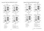
Page 16: ...ts the WinPower software will appear as a green plug icon located in the system tray near the clock Appendix 1 Rear Panel of 1KVA Tower UPS WinPower is a brand new UPS monitoring software which provides user friendly interface to monitor and control your UPS This unique software provides safely auto shutdown for multi computer systems while power failure With this software users can monitor and co...

Page 17: ...Breaker AC Input SCHUKO IEC 320 UNIVERSAL NEMA E P O Port Intelligent Slot Optional Output Socket Output Terminal Optional 701 0071581 UPS AplusB 9200LB E 01 29 USB Port Cooling Fan Input Breaker AC Input E P O Port Intelligent Slot Optional Output Socket Output Terminal Optional AUSTRALIAN UK FRENCH UNIVERSAL NEMA 30 ...

Reviews: