background image

Page 56 of 60 

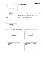
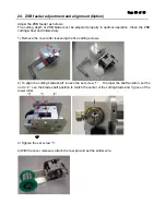
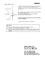
5) Push down solder clamp lever and feed the solder wire.    Make sure the cutting blade makes 
holes on the center of the solder wire.    If the holes were not on the center, adjust the cutting blade 
shaft position, then re-feed the solder wire and re-check it. 


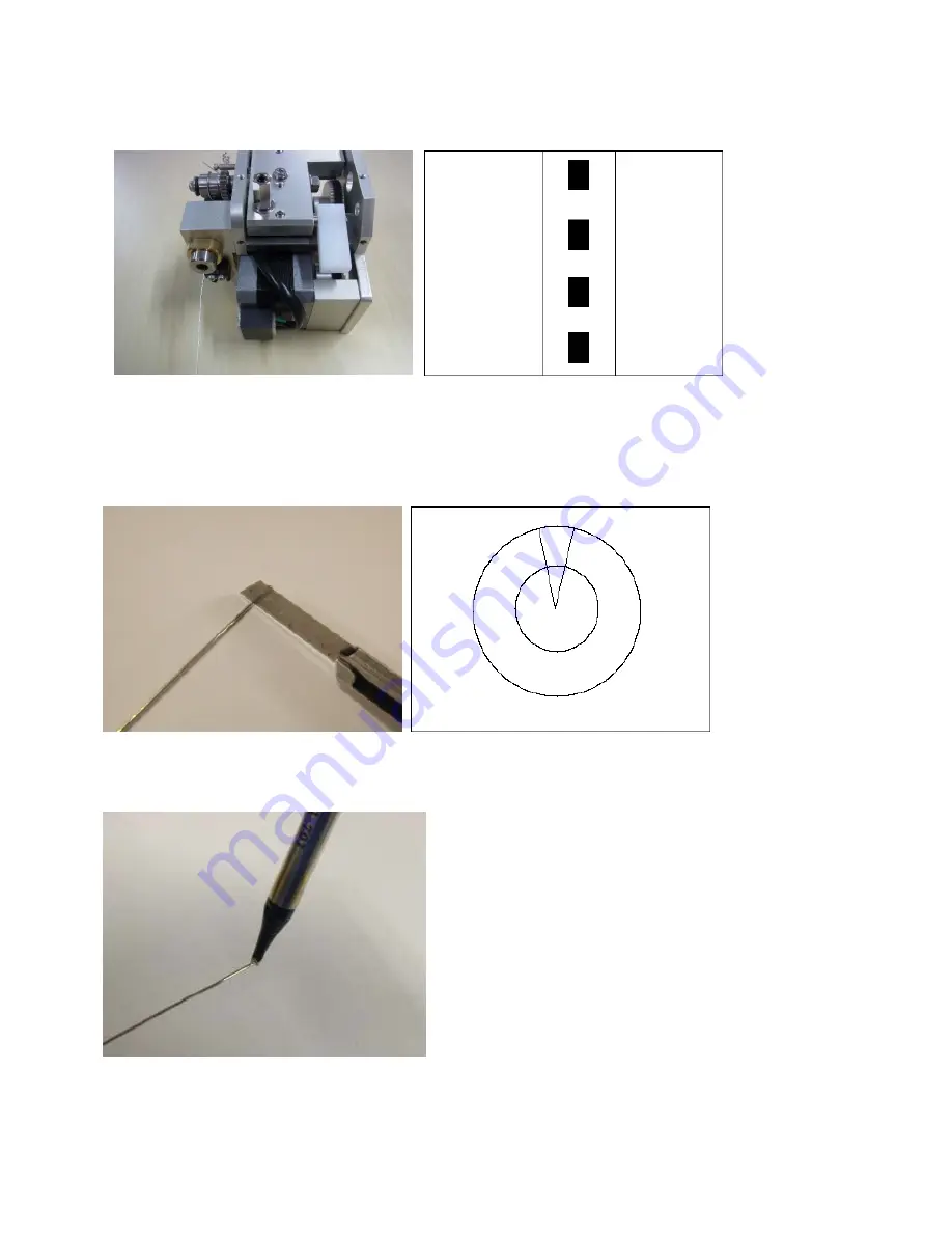
6) Cut the solder wire with holes perpendicularly and check the cross section. Make sure the cutting 
blade penetrates into flux core.   
If the cutting depth was not enough or too deep, loosen the nut “4” then adjust the adjusting screw 
“3” for the cutting depth to penetrate into flux core. 
Repeat until desired depth is acquired. 


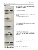
7) Complete adjustment and the alignment of the cutting blade and increase the temperature of 
iron tip. Melt the solder wire with holes, and make sure the flux is coming out the holes. 


8) Put the cover back and tighten five set screws. 


Summary of Contents for J-CAT200 COMET

Page 1: ...u for purchasing the J CAT COMET Read these instructions thoroughly for proper use of this machine Make sure to read Safety Notes before you use machine This information protects you from possible dan...

Page 2: ...iron cartridge Please handle this machine with care If the machine is dropped or sustains great impact vibration it may cause malfunction If you do not use the machine for a long time Please turn off...

Page 3: ...18 11 Point Soldering Program Setting 19 12 Slide Soldering Program Setting 22 13 Easy Slide Soldering Program Setting 28 14 The Other Program Setting 29 15 Point Type List 33 16 How To Save The Teac...

Page 4: ...table Weight 7 0kg 11 0kg Maximum Speed X Y Axes 700mm sec 800mm sec Z Axis 250mm sec 320mm sec R Axis 600 sec 800 sec Repeatability X Y Z Axes 0 01mm R Axis 0 008 Teaching Method Remote teaching JOG...

Page 5: ...Page 5 of 60 3 Dimensions J CAT200 COMET...

Page 6: ...Page 6 of 60 J CAT300 COMET...

Page 7: ...Page 7 of 60 J CAT400 COMET...

Page 8: ...Page 8 of 60 J CAT500 COMET...

Page 9: ...00 COMET COMET controller Emergency stop switch Program selection key Start button Iron unit Solder feeder Solder tube Teaching Pendant Program number display Solder wire position adjusting screws Bac...

Page 10: ...olding it the down position While teaching the soldering position the position can be checked with this button 3 Solder feed forward button Solder wire is forwarded while this button is pressed 4 Powe...

Page 11: ...ron Unit 4 Solder wire feeding position can be adjusted Upper adjusting screw Up down direction Lower adjusting screw Left right direction 5 Iron up down speed can be adjusted by turning screws after...

Page 12: ...rm lower limit setting Use or key to change 0 500 50 PASS flash Password setting No need to set Temperature calibration PVS1 Make sure to carry out after replacing iron cartridge MODE FUNC MODE FUNC M...

Page 13: ...ss until above screen appears Press once Press for 2 sec to return Change value by Temperature alarm lower limit E2H Press for 4 sec Press until above screen appears Press twice Press for 2 sec to ret...

Page 14: ...obot by Teaching Start up preparation Program number selection Point coordinates input Point type selection Soldering condition number input Soldering condition input Test Running Point teaching Repea...

Page 15: ...ch Run Mode for running program Select Teaching Mode for Teaching Then press ENTER In order to run program make sure that LED of Start button is flashing Then press Start button External Run Mode To s...

Page 16: ...to the motor will be turned off and the robot will stop running by pressing this button Also during soldering the soldering will be stopped and the iron tip will go up How to release the emergency sto...

Page 17: ...number LIST Displays the list of set program number GLIST Shows the programmed teaching point on the sreen For setting the new program number press in order to display the unset program number list Se...

Page 18: ...to the home position By F2 and F3 keys the mode can be switched between JOG and MDI Mode One Touch Feed Length Refer to Soldering System Setting page By pressing and holding solder wire is fed in rev...

Page 19: ...n and heats the joint substrate Pre heat time depends on the size of joint substrate 2nd solder amount speed Set 2nd solder amount and feed speed that the joint requires Although 2nd solder amount dep...

Page 20: ...set soldering condition number VIEW Shows the soldering condition of the displayed number Refer to the next page If the solderting condition is not set initial value is displayed The programmed solde...

Page 21: ...oldering point has been registered and the next point screen is displayed Soldering condition can be also enterd in Soldering condition by pressing MENU key at Teaching mode Soldering Condition 1 1 2...

Page 22: ...Start pool time It is the solder pooling time before sliding start The sliding starts after the set pool time 2nd solder amount 1 speed 1 Set 2nd solder amount and feed speed that the joint requires...

Page 23: ...unset soldering condition number LIST Displays the list of set soldering condition number VIEW to check the soldering condition of the displayed number Refer to the next page If the solderting conditi...

Page 24: ...g Condition 1 1 2 Soldering Type Line Soldering 1st Amount 7mm 1st Feed Speed 15mm s 1st Rev Amount 3mm 1st Rev Speed 50mm s Pre Heat Time 0 5sec 2nd Amount 1 10mm 2nd Feed Speed 1 15mm s 2nd Amount 2...

Page 25: ...registered and the next point screen is displayed Enter a number Line Speed 10mm s Program1 P1 X 0mm Y 0mm Z 0mm R 0deg FUNC JOG MDI INIT Select Point Type 1 4 Point Soldering Point Soldering No Up St...

Page 26: ...d and the next point screen is displayed Enter a number Line Speed 10mm s Program1 P1 X 0mm Y 0mm Z 0mm R 0deg FUNC JOG MDI INIT Select Point Type 1 4 Point Soldering Point Soldering No Up Start of Li...

Page 27: ...Teaching example Program1 P2 X 0mm Y 0mm Z 0mm R 0deg FUNC JOG MDI INIT Program1 P1 X 0mm Y 0mm Z 0mm R 0deg FUNC JOG MDI INIT Select Point Type 1 4 Point Soldering Point Soldering No Up Start of Line...

Page 28: ...of joint substrate Start pool time It is the solder pooling time before sliding start The sliding stats after the set pool time 2nd solder feed speed Set 2nd solder feed speed that the joint requires...

Page 29: ...the same number as the point slide soldering condition Press ENTER Pre Solder point has been registered and the next point screen is displayed Enter a number Condition Number 1 DEL COPY NEW LIST VIEW...

Page 30: ...leaning Point has been registered and the next point screen is displayed Enter a number Cleaning 1 sec DEL COPY NEW LIST VIEW Program1 P1 X 0mm Y 0mm Z 0mm R 0deg FUNC JOG MDI INIT Select Point Type 1...

Page 31: ...error Aftre power on emergency stop or after opreation mode is switched Call Program is always carried out in the 1st cycle The count is cleared after power off or operation mode is switched e g Clean...

Page 32: ...the type PTP Evasion Point by CURSOR key Page 2 is displayed by SHIFT key Press ENTER PTP Evasion Point has been registered and the next point screen is displayed Program1 P1 X 0mm Y 0mm Z 0mm R 0deg...

Page 33: ...Point CP Arc Point End of Easy Line Soldering CP End Point After moving to the teaching point by CP drive soldering is executed with the programmed remaining soldering condition Pre Solder PTP Point P...

Page 34: ...ing point the robot waits the start button is pushed Standby Point on Error PTP Drive Point Job CP Start Point General CP drive point CP Passing Point General CP passing point CP Stop Point General CP...

Page 35: ...PC Soft Before using JR C Points save the programmed data at first then send a new data If not the data may be deleted If the updated data is sent to the robot from PC the current data in the robot is...

Page 36: ...m s 1st Rev Amount 3 0mm 0 99 9mm 1st Rev Speed 50 0mm s 1 50 0mm s Pre Heat Time 0 5sec 0 9 9sec 2nd Amount1 10 0mm 0 99 9mm 2nd Feed Speed1 15 0mm s 1 50 0mm s 2nd Amount2 0 0mm 0 99 9mm 2nd Feed Sp...

Page 37: ...n and select the point type Each point that comes after the inserted point shifts down by one number 18 2 Delete a Point The created point can be deleted Display the setting screen for the point to be...

Page 38: ...int in the program is entered Select the Block Editing menu Editing Points Menu Insert a Point Delete a point Block Editing Block Setting Same Value Transform into Relative Block Editing Enter a numbe...

Page 39: ...to the other programs Select Move Block Points form the Block Editing Menu The screen on the right is shown Enter the Destination Point Number The specified block moves forward to the Destination Poin...

Page 40: ...Distance the screen moves to Y Distance entry Screen Enter the number of times to copy The block copy is executed and the screen returns to the setting screen The copied block points are inserted behi...

Page 41: ...unnecessary axis shifting distance The offset value adds to all the points in the block points Then the screen returns to the point setting screen The coordinates after offset may exceed the operation...

Page 42: ...e 99999 The maximum count value 99999 Soldering System Settings Enter a number Iron Shot Counter 10000 Soldering System Settings IO Function Assignment Iron Shot Counter Disable Cycle Count Disable On...

Page 43: ...the current value becomes bigger value than maximum iron shot number 19 1 2 Iron Shot Counter Reset How to reset Iron Shot Counter Press MENU key at teaching mode and select Soldering System Settings...

Page 44: ...lows During External operation mode or Switch run mode it is counted at the time running program ends 1 cycle then it is displayed on teaching pendant The cycle count value is not updated during robot...

Page 45: ...ered length to avoid solder wire overrun By pressing 9 on teaching pendant the solder wire can be fed Soldering System Settings IO Function Assignment Iron Shot Counter Disable Cycle Count Enable Cycl...

Page 46: ...mode and select Soldering System Settings Then select Type of Error Reset and press ENTER Select START BUTTON or I O SYS START BUTTON Resetting by pressing the start button on the robot Set Switch Ru...

Page 47: ...nal Run Mode Program1 Running In Cycle Start Signal Waiting External Run Mode Program1 Running In Cycle Start Signal Waiting Go to Home e g Solder clogged error After the reset button signal is input...

Page 48: ...ss MENU key at texching mode and select Soldering System Settings Then select Manual Feed Speed and press ENTER Enter the speed value Setting range is 1mm sec 50mm sec Soldering System Settings IO Fun...

Page 49: ...e 13 sys In 14 Ex Error Reset Free Start Inhibition Stop Start Inhibition Soft Lock Emergency Stop 14 sys In 15 Tip ADJ Z sensor Free 15 sys In 16 Tip ADJ X Y sensor Free 16 Output sys Out 1 BRC 3000...

Page 50: ...ut 7 Air Blow 19 gen Out 8 EMERGENCY 20 Others COM DC24V 21 COM DC24V 22 COM GND 23 COM GND 24 How to change I O SYS Function Assignment It is possible to change the I O SYS function assignment of the...

Page 51: ...is input the robot starts operating according to the setting of Type of restart in Soldering System Settings Input sys In 1 Start sys In 2 Free sys In 3 Program No LOAD sys In 4 10 Progra No sys In 11...

Page 52: ...ron Cartridge Breaking of iron tip heater Replace new iron cartridge 26 How To Change Iron Cartridge Thermocouple is damaged The range between temperature alarm upper value and lower value is small En...

Page 53: ...er and input proper value Control PCB is damaged Contact to Apollo Seiko or our agency for repair Solder is not properly fed The release lever is upper position Lower the release lever The feeding cut...

Page 54: ...If these items check out to be OK there may be a malfunction with the heater 4 Air pressure Check for sufficient air pressure 0 5MPa 5 Feed tube clog If the solder clogs near the feeder remove the tu...

Page 55: ...wheel and rollers daily 1 Remove the cover after loosening the five setting screws 2 To align the cutting blade shaft loosen the set screw 1 To adjust the shaft position set the nut to 2 ove the blad...

Page 56: ...ularly and check the cross section Make sure the cutting blade penetrates into flux core If the cutting depth was not enough or too deep loosen the nut 4 then adjust the adjusting screw 3 for the cutt...

Page 57: ...C or if solder with a bad solder feeding position the life is shorten extremely to approximately 5 000 points caused by Iron plate Corrosion Therefore please use it with suitable condition If the con...

Page 58: ...tip by the corrosion of chloride element in flux and wear phoenomenon 2 Check for soldering defect Imperfection of electric connection by of flux membrane Clean the surface and make iron tip temperatu...

Page 59: ...has been applied and insert a new X tip 5 As shown on the left the top of DCX HET has not been covered with burning inhibitor substance In order to apply burning inhibitor substance on DCX HET re inse...

Page 60: ...key is in the incorrect position or the key is damaged 2 Slip the silicon ring over the iron cartridge Apollo Seiko Ltd 2271 7 Jinba Gotenba shi Shizuoka Japan 412 0047 TEL 81 0 550 88 2828 FAX 81 0...

Reviews: