background image

Operating Manual 


32 


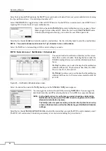
Selecting 

Schedule On

 toggles between On and Off.  In the Schedule On mode, the DVR records video based on the 

schedule established in the Schedule screen.  When turning Schedule recording Off, you will be asked to confirm your 
decision, and   displays at the top-left corner of each camera screen.  Panic recording will function even when Schedule 
is turned off.    displays during panic recording. 


Select the 

Schedule Mode 

box and select 

between Simple Mode

 and 

Advanced Mode

.  Selecting 

Advanced Mode


allows you to set up individual recording schedule for each event. 


NOTE:  Changing the schedule mode will reset all event and action statuses. 


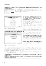
Select the 

+

 to add a schedule item. 


Select the box under the 

Day

 heading to change the days that the scheduled recording will take place.  Choose from: 

Sun

,

 Mon

,

 Tue

,

 Wed

,

 Thu

,

 Fri

,

 Sat

,

 M~F

,

 Hol

 and 

All


Select the box under the 

Range

 heading to change the time range that the scheduled recording will take place.  The 

smallest time segment you can use is 15 minutes.  


Select the box under the 

Mode

 heading to change the recording mode that will be used.  Choose from: 

No Record

,


Time

,

 Event 

and

 Time & Event

. (Simple Mode Only) 


When the DVR is in the 

No Record

 mode, it will not record during the preset day and time range except the panic recording.  

Use the 

No Record

 mode when you do NOT want the DVR to record during certain times. 


When the DVR is in the 

Time 

mode, the   icon displays at the top-left corner of the screen.  The DVR will record 

and displays the   icon at the top-left corner of the screen during the scheduled times. 


When the DVR is in the 

Event 

mode, the red   icon displays at the top-left corner of the screen.  The DVR will record 

and displays the   icon at the top-left corner of the screen when any event occurs.  When the DVR is in the 

Pre-Event


recoding mode, the yellow   icon displays when there is no event, and the DVR is not recording.  When the DVR is 
in the 

Pre-Event 

mode, the red   and   display when any event occurs and the DVR starts recoding. 


When the DVR is in the 

Time & Event

 mode, the DVR will follow the Time settings and the   icon displays at the 

top-left corner of the screen.  The DVR follows the Event settings and the   icon displays. 


Select the box under the 

Channels 

heading to select which cameras will be recorded. (Simple Mode Only) 


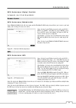
Select the box under the 

Settings 

heading


to define the recording settings. 


You can set the ips, Quality and Resolution (ips, Quality, 
Resolution and Dwell for Advanced Mode setup) of the 
recording for any modes you set up in the Mode column.  If 
you do not set the ips, Quality, Resolution and Dwell in the 
Settings column, the DVR will follow the default settings.  
See below for details. 


NOTE:


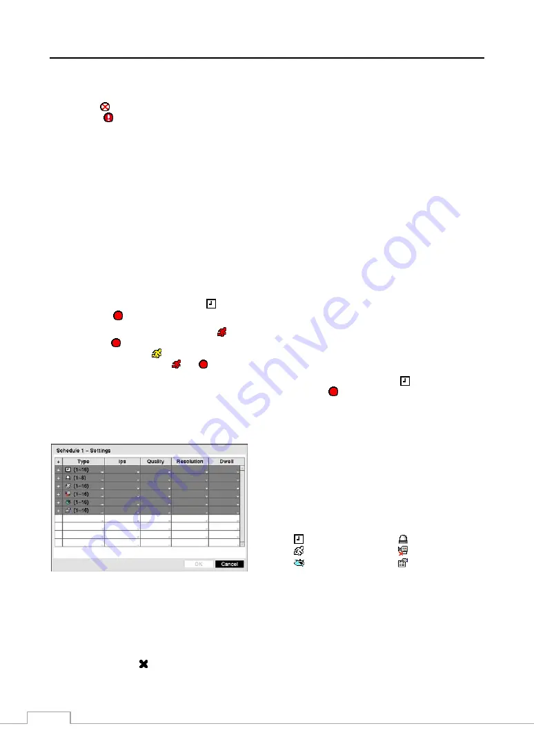
Descriptions of the Record icons in the Type 
column are as follows: 


  Time-lapse (Time)


  Alarm-In


  Motion


  Video Loss


  Video Blind


  Text-In 


Figure 41 — Schedule – Settings (Advanced Mode) setup screen. 


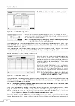
NOTE:  Channels that are not defined will use the setting values of the previous schedule item. 
 

When multiple events are detected at the same time from a specific channel, the DVR will record event 
video with the high setting values if the ips, Quality, Resolution and Dwell values of events are different 
from each other.  However, the ips will be reset to the supported maximum value when the ips, Quality, 
Resolution and Dwell are all set to the highest value. (Advanced Mode Only) 


Select the box under the 


heading


to delete the recording settings.  You will be asked to confirm that you want to delete 

the settings. 


Summary of Contents for MRH Series

Page 1: ...MRH Series Digital Video Recorders Mobile Digital Video Systems User Guide and Instruction Manual Version 1 5 ...

Page 2: ......

Page 3: ...T GENERATES USES AND CAN RADIATE RADIO FREQUENCY ENERGY AND IF NOT INSTALLED AND USED IN ACCORDANCE WITH THE INSTRUCTION MANUAL MAY CAUSE HARMFUL INTERFERENCE TO RADIO COMMUNICATIONS OPERATION OF THIS EQUIPMENT IN A RESIDENTIAL AREA IS LIKELY TO CAUSE HARMFUL INTERFERENCE IN WHICH CASE USERS WILL BE REQUIRED TO CORRECT THE INTERFERENCE AT THEIR OWN EXPENSE WARNING CHANGES OR MODIFICATIONS NOT EXPR...

Page 4: ...indicates a need for service 13 Replacement Parts When replacement parts are required be sure the service technician has used replacement parts specified by the manufacturer or that have the same characteristics as the original part Unauthorized substitutions may result in fire electric shock or other hazards 14 Safety Check Upon completion of any service or repairs to this equipment ask the servi...

Page 5: ...Port 6 RS485 Port 6 LED 6 Alarm Input Output 6 Panic 7 Network Port 7 Factory Reset Switch 7 Chapter 3 Configuration 9 Front Panel Controls 9 HDD Rack 9 Power Switch 9 USB Port 9 Power LED 9 Record LED 9 Turning on the Power 10 Turning off the Power 10 Initial Unit Setup 10 Setup Screen 11 System Setup 12 Information 12 Date Time 13 Storage 15 User 16 Power Management 18 Shutdown 19 Network Setup ...

Page 6: ...46 PTZ Mode 46 Event Monitoring 47 Covert Camera 47 Display Menu 48 Recording Video 49 Panic Recording 49 Recording Audio 49 Playing Recorded Video 49 Searching Video 50 Search Menu 50 Event Log Search 52 Record Table Search 53 Calendar Search 54 Motion Search 55 Text In Search 56 Clip Copy 57 Appendix 59 USB Hard Disk Drive Preparation 59 Text In Search Examples 59 Search Example I 59 Search Exam...

Page 7: ...een 20 Figure 21 DVRNS setup screen 21 Figure 22 RTSP setup screen 22 Figure 23 Notification Callback setup screen 23 Figure 24 Notification Mail setup screen 23 Figure 25 Notification Schedule setup screen 24 Figure 26 Devices menu 25 Figure 27 Camera setup screen 25 Figure 28 Camera PTZ setup screen 25 Figure 29 Audio setup screen 26 Figure 30 Alarm Out Settings screen 26 Figure 31 Alarm Out Sch...

Page 8: ...Actions screen 40 Figure 55 Health Check screen 40 Figure 56 Storage screen 41 Figure 57 System Event Actions screen 41 Figure 58 Event Status screen 42 Figure 59 Live Monitoring menu 44 Figure 60 PTZ Preset menu 47 Figure 61 Display menu 48 Figure 62 Select Playback Camera menu 49 Figure 63 Search menu 50 Figure 64 Event Log Search screen 52 Figure 65 Record Table Search screen 53 Figure 66 Calen...

Page 9: ...r Interface GUI Menu System Multiple Recording Modes Time lapse Pre event Event and Panic Two way Audio Communication 2 Channel Audio Recording and 1 Channel Audio Playback Supports GPS Input Text Input for ATM POS Alarm Connections Include Input Output and Reset Input Live or Recorded Video Access via Ethernet Time Synchronization using industry standard protocol Self diagnostics with automatic n...

Page 10: ...o clips to external hard disk and flash drives Figure 1 Typical DVR installation NOTE This manual covers the 4 8 and 16 channel digital video recorders The DVRs are identical except for the number of cameras that can be connected and the number of cameras that can be displayed For simplicity the illustrations and descriptions in this manual refer to the 16 camera model ...

Page 11: ...REAK LOOSE AND CAUSE INJURY IN THE EVENT OF AN ACCIDENT CAUTION The DVR must be mounted level using the bracket to attach it to the floor The DVR must NOT be mounted on its side or upside down The vibration isolation mounts are not designed to support the DVR if it is mounted on its side or upside down Figure 2 Typical Mounting CAUTION The rubber collars of the vibration isolation mounts are betwe...

Page 12: ...NT THAT THE MONITOR AMPLIFIER AND CABLES DO NOT INTERFERE WITH ANY OF THE VEHICLE S CONTROLS IT IS ALSO IMPORTANT THAT THEY DO NOT BLOCK THE DRIVER S VIEW OR REACH FAILING TO HEED THESE WARNINGS COULD CAUSE AN ACCIDENT CAUSING SERIOUS INJURY OR DEATH Video Input Connect the coaxial cables from the video sources to the BNC Video In connectors Audio In Out NOTE It is the user s responsibility to det...

Page 13: ...ing the ignition off timeout Refer to Chapter 3 Configuration System Setup for details CAUTION Even if you do not plan to use the ignition off timeout feature it is important to connect Pins 1 2 and 3 The DVR uses power from these pins for purposes in addition to the ignition off timeout and it will not function properly if they are not connected Pins 5 6 7 and 8 should be connected directly to gr...

Page 14: ...o signal the DVR to react to events Mechanical or electrical switches can be wired to the AI Alarm In and GND Ground connectors The voltage range is from 0V to 50V When the electrical switch is wired the threshold voltage for NC Normally Closed is below 2 4V and for NO Normally Open is above 2 8V and it should be stable at least 0 5 seconds to be detected See Chapter 3 Configuration for configurin...

Page 15: ...nded for outdoor use Factory Reset Switch The DVR has a Factory Reset switch to the right of the Network port on the rear panel This switch will only be used on the rare occasions that you want to return all the settings to the original factory settings CAUTION When using the Factory Reset you will lose any settings you have saved To reset the unit you will need a straightened paperclip 1 Turn the...

Page 16: ...Operating Manual 8 ...

Page 17: ...rsonal computer Power Switch The unit can be turned on or off with the key provided with the unit USB Port Two USB ports on the front panel are provided to connect external hard disk or flash drives for video clip copying or system upgrades Position external drives close enough to the DVR so that you can make the cable connections usually less than 6 feet Use the USB cable provided with the hard d...

Page 18: ...n or shutoff WARNING DO NOT TOUCH THE BOTTOM OR TOP OF THE REMOVABLE HARD DISK DRIVE WHEN REMOVING IT AFTER THE BUILT IN HEATER OPERATES IN THE LOW TEMPERATURE CONDITION WHEN THE HEATER OPERATES THE TEMPERATURE OF THE HARD DISK DRIVE INCREASES HIGH AND TOUCHING THE BOTTOM OR TOP OF IT MAY CAUSE INJURY Turning off the Power The DVR can be turned off by rotating the key counter clockwise to the Off ...

Page 19: ...rd is strongly recommended To log the user out of the system move the mouse pointer to the top of the screen and then select Logout in the Live Monitoring menu The Logout screen displays asking you to confirm whether or not you want to log out the current user Setup Screen Figure 6 Setup screen Move the mouse pointer to the top of the screen and then select Setup in the Live Monitoring menu to ent...

Page 20: ... or more DVRs that are in the same RS485 network It is possible to have multiple DVRs with System ID 0 that are in the same area as long as they are not part of an RS485 network If this is the case all will be controlled at the same time when using the infrared remote control Select the box beside Language and a drop down menu displays the available languages Select the desired language The box be...

Page 21: ...play the System Log The System Log screen lists system activities up to 5 000 from the latest that have occurred along with the time and date The icon will be displayed in the last column for system activities of the remote site You can scroll through the log pages by using the Up and Down arrows or you can go directly to a log page by entering the log page number in the box at the bottom left of ...

Page 22: ... Date Time Holiday tab You can set up holidays by selecting The current date appears Select the month and day and change them by using the Up and Down arrows Dates can be deleted by selecting the beside the date NOTE Holidays that do not fall on the same date each year should be updated once the current year s holiday has passed Figure 10 Holiday setup screen PATH System menu Date Time Time Sync t...

Page 23: ...ice will not be used for recording You can also set aside space to store temporary files for CD or DVD burning by selecting Partition CD DVD Burn NOTE The DVR does NOT support USB hard disk drives with a version lower than 2 0 The Information column displays whether the device is being used or not Other indicates the device has been used for another DVR Select the box in the Information column for...

Page 24: ...e screen displays and you can check the storage condition for details Once the Bad message displays replacing the hard disk drive is recommended usually within 24 hours Temperature and S M A R T information will be available only for the internal hard disk drive supporting the SMART Self Monitoring Analysis and Reporting Technology monitoring program PATH System menu Storage Setup tab Figure 14 St...

Page 25: ...hat can be turned On and Off are Shutdown The user can shut the system down on a local system Upgrade The user can upgrade the software on a local system or a PC running RAS Color Control The user can control brightness contrast hue and saturation for cameras on a local system or a PC running RAS System Check The user can view the remote system status or check the remote system status as a batch p...

Page 26: ...n the saved information Selecting the box beside Boot Up and changing the number by using the Up and Down arrows allows you to change the range of the battery power voltage for powering up the DVR When the battery power voltage is out of the Boot Up voltage range the DVR will not power up Selecting the box beside Shutdown and changing the number by using the Up and Down arrows allows you to change...

Page 27: ... D1 and Standard CIF Figure 19 Network setup screen NOTE The higher Quality and Resolution settings require higher Transfer Speed settings The transfer speed you set is the maximum speed Depending on the network environment this speed may not be achieved You can limit the network bandwidth settings so that system does not consume too much network bandwidth Select the box beside Network Bandwidth L...

Page 28: ...wn arrows to set the IP address of the DNS server Select Use UPnP to toggle between On and Off When it is On port forwarding from the NAT Network Address Translation device to the DVR will be enabled automatically via UPnP Universal Plug and Play service This function will be used especially when accessing to a port on a private IP address NOTE For the UPnP service to work the NAT device should su...

Page 29: ...ht change whenever the unit is turned on PATH Network menu Network DVRNS tab Select Use DVR Name Service to toggle between On and Off NOTE The DVRNS DVR Name Service allows the DVR to use Dynamic IP addresses for remote connection When this feature is On you can access your DVR remotely using the DVR name instead of its IP address For the DVRNS feature the DVR should be registered on the DVRNS ser...

Page 30: ... by using the Up and Down arrows Select the box beside RTSP End Port and set the end port number of the RTP server obtained from your system administrator by using the Up and Down arrows Select Use Mobile to toggle between On and Off When set to on you can access a remote DVR using a Blackberry or other mobile devices Select the box beside Mobile Port and set the port number of the web server obta...

Page 31: ... a mail recipient Select the first box under Recipient and a virtual keyboard appears that you can use to enter the recipient s e mail address Select the second box under Recipient and select between Manual and listed SMTP mail server providers NOTE The e mail address must include the character to be a valid address Select the box under the heading to toggle between On and Off The DVR will clip an...

Page 32: ...the Column heading allows you to edit the information in those boxes The Day box allows you to select the days that the notification schedule will be active The choices are Sun Mon Tue Wed Thu Fri Sat M F Hol and All The Range box allows you to set the time that the notification schedule will be active in 15 minute increments from 00 00 to 24 00 Figure 25 Notification Schedule setup screen Select ...

Page 33: ...ert video When selecting the Covert 2 the DVR displays only camera title on the covert video NOTE A user who does not have Covert Camera View authority cannot view video from cameras set to Covert 1 or Covert 2 in both the live monitoring and playback modes PATH Devices menu Camera PTZ tab NOTE You will only be able to set up PTZ devices if the PTZ port is set to RS232 or RS485 Figure 28 Camera PT...

Page 34: ...an select which camera you want associated with that audio input You cannot associate the same camera with two audio inputs Selecting Enable Audio Out toggles between enabling and disabling audio out Figure 29 Audio setup screen Alarm Out PATH Devices menu Alarm Out Settings tab Each alarm output can be given its own title by selecting the box under the Title heading A virtual keyboard appears all...

Page 35: ...items can be turned On or Off Zoom The icon displays on the enlarged video Network The icon displays when the unit is connected to a network via Ethernet The icon displays on each camera when audio communication is available between the DVR and a PC running RAS via Ethernet Freeze Sequence The icon displays while in the Freeze mode and the displays while in the Sequence mode Screen Group The numbe...

Page 36: ...hannel models only Selecting Sequence in the Live Monitoring menu causes the DVR to sequence cameras and the DVR can sequence cameras in two modes Full and Cameo In the Full mode the DVR sequences through the cameras and displays them full screen In the Cameo mode the bottom right window in a multi screen format sequences through the cameras NOTE Any cameras that are Off have lost video or are set...

Page 37: ...ntrol networking text input or remote control the GPS cannot be configured Select Setup and select the correct Baud Rate Parity Data Bits and Stop Bits for the device you are connecting to the DVR Use the GPS manufacturer s recommended settings when configuring the RS232 or RS485 ports Selecting Enable Recording toggles On and Off When set to On the DVR will record images with GPS information Sele...

Page 38: ... these horizontal scan lines and flashes The DVR can record up to two audio inputs Selecting Record Audio toggles between On and Off Select the slide bar beside Auto Deletion and use the slider bar or Up and Down arrows to adjust the length of time recorded data will be kept from 1 to 999 days The DVR automatically deletes video recorded earlier than the user defined period under three conditions ...

Page 39: ...ff Select the Panic Recording Duration box and set the duration of panic recording Panic recording will stop automatically after the preset duration unless you stop the panic recording manually You can set the dwell from 5 minutes to 1 hour Select No Limit if you want to stop panic recording manually Selecting the Panic Recording ips allows you to set the images per second for Panic recording You ...

Page 40: ... corner of the screen The DVR will record and displays the icon at the top left corner of the screen when any event occurs When the DVR is in the Pre Event recoding mode the yellow icon displays when there is no event and the DVR is not recording When the DVR is in the Pre Event mode the red and display when any event occurs and the DVR starts recoding When the DVR is in the Time Event mode the DV...

Page 41: ...o not have Event set up in the Record Schedule a message will display alerting you to this fact Figure 42 Pre Event setup screen When the DVR is in the Event Record mode it is possible to have it record images before the event occurs The Pre Event screen allows you to define how to handle pre event recording You can turn individual cameras On or Off for pre event recording The image speed can be s...

Page 42: ...one of its alarm input connectors Select the desired box under the Record heading and a list of cameras appears Select the cameras that you want the DVR to record whenever it detects an input on the associated alarm input NOTE For the Record action the camera you select should be set to the Event or Time Event recording mode in the Record Schedule setup screen Figure 45 Alarm In Actions screen Sel...

Page 43: ...nd dragging the pointer to where you want to end the zone and individual blocks are selected or cleared by clicking the mouse button Click the mouse right button to display the menu screen The menu on the setup screen has the following functions Select Activates selected blocks to detect motion Clear Deactivates selected blocks so that they will not detect motion Reverse Activates inactive selecte...

Page 44: ...u wish If the DVR detects motion on the selected camera it starts recording video from all the associated cameras NOTE For the Record action the camera you select should be set to the Event or Time Event recording mode in the Record Schedule setup screen Figure 47 Motion Detection Actions 1 screen Select the box under the Alarm Out heading and a list of Alarm Outputs appears You can associate as m...

Page 45: ... recording video from all the associated cameras NOTE For the Record action the camera you select should be set to the Event or Time Event recording mode in the Record Schedule setup screen Select the box under the Alarm Out heading and a list of Alarm Outputs appears You can associate as many Alarm Outs with that camera as you wish When the DVR detects video loss on the selected camera it will tr...

Page 46: ...lect the box under the Record heading and a list of cameras appears You can associate as many cameras with that camera as you wish If the DVR detects video blind on the selected camera it starts recording video from all the associated cameras NOTE For the Record action the camera you select should be set to the Event or Time Event recording mode in the Record Schedule setup screen Select the box u...

Page 47: ...f text input devices and there will be different parameter boxes for you to enter information Select the box beside Transaction Start and enter the Transaction Start string by using the virtual keyboard Refer to the device manufacturer s documentation for the text string that the device first sends when a transaction starts If you want the DVR to react to any character sent from the text input dev...

Page 48: ...vent recording mode in the Record Schedule setup screen Select the box beside Alarm Out and a list of Alarm Outputs appears You can associate as many Alarm Outs with the Text Input as you wish When the DVR detects text input it triggers output signals on all the associated Alarm Out connectors NOTE For the Alarm Out action the alarm output and beep you select should be set to the Event mode in the...

Page 49: ...hrough the numbers by using the Up and Down arrows to Refer to the hard disk drive manufacturer s documentation for the correct temperature setting If the temperature of hard disk drive exceeds the defined threshold the system triggers an alert Select the second box beside Disk S M A R T and select either ºC Celsius or ºF Fahrenheit PATH Event menu System Event Actions tab Figure 57 System Event A...

Page 50: ...he panic recording mode Disk Almost Full will be highlighted when the DVR is not in the Recycle mode and the level of disk usage reaches the Disk Almost Full percentage you made in the System Event setup screen on the Event menu Disk Full will be highlighted when the DVR is not in the Recycle mode and all available storage space has been used Disk Config Change will be highlighted when a storage d...

Page 51: ...is out of the range set during System menu Power Management There is 2 5V or more of voltage difference between the accessory and battery power When the DVR turns on after the emergency shutdown or shutoff the battery power voltage does not keep the range from 11 5V or higher to lower than 32V for longer than the time set during System menu Power Management In this case you can turn on the DVR by ...

Page 52: ...the icon displays in bottom left corner if Freeze is selected in the Display setup screen OSD tab Sequence Selecting Sequence in the Live Monitoring menu causes the cameras to display sequentially When in one of the multi view formats pressing this button will cause the DVR to go through predefined screen layouts Full Sequence Or the bottom right screen will display live cameras sequentially Cameo...

Page 53: ...n the Live Monitoring menu resets the DVR s outputs during an alarm Panic Selecting Panic in the Live Monitoring menu starts panic recording of all cameras and selecting again stops panic recording Setup Selecting Setup in the Live Monitoring menu enters the Main Setup screen Refer to Chapter 3 Configuration for detailed descriptions of system setup Search Mode Selecting Search Mode in the Live Mo...

Page 54: ...n the screen A rectangle shows the area that will be enlarged You can move the rectangle around by holding down the mouse button and dragging the pointer In the Zoom mode click the mouse right button and select the enlargement ratio in the menu or scroll mouse wheel and down enlarges the area in rectangle Exit the Zoom mode by selecting Zoom again in the Camera Menu While in the Zoom mode the icon...

Page 55: ...meras on a 2x2 screen If five to nine cameras are associated with the event the DVR will display the cameras on a 1P5 1P7 or 3x3 screen If 10 or more cameras are associated with the event the DVR will display the cameras on a 4x4 screen Event monitoring lasts for the dwell time set for event recording After the dwell time has elapsed the monitor returns to the previous screen unless another event ...

Page 56: ...5 or 1P7 display mode the main channel indicates the channel displayed on the large screen which is displayed in the top left You can select the camera you want to display on the main channel screen Select a channel on the screen and click the mouse right button to display the Camera Menu Selecting Go To Main swaps the selected channel with the main channel This function is supported only in the 1...

Page 57: ... When the DVR is not in the Recycle mode and all available storage space has been used panic recording will not operate Recording Audio If the DVR was set up to record audio it will record audio from up to four inputs when video is recording NOTE Make certain you comply with all local and federal laws and regulations when recording audio Playing Recorded Video If a user who has Search authority lo...

Page 58: ...the screen displays the following Search menu You can select menus and items by clicking the mouse left button Search Go To Bookmarks Export Camera Menu Alarm Reset Panic Exit Figure 63 Search menu Search Menu Search Selecting Search in the Search menu displays the following Search menu See the following Event Log Search Record Table Search Calendar Search Motion Search and Text In Search sections...

Page 59: ...ers the active cameo mode 8 and 16 channel models only Select Edit Group and choose a camera that you want to change display position e g Camera A Then click the mouse right button to display the menu If you choose another camera in the menu e g Camera B the screen displays Camera B instead of Camera A Clicking the mouse right button and selecting Exit Group Edit in the menu exits the Active Cameo...

Page 60: ...t in the Search menu returns to live monitoring NOTE It is possible that no recorded image displays on the current screen Select 4x4 for the 16 channel DVR 3x3 for the 8 channel DVR and 2x2 for the 4 channel DVR in the Mouse Display menu and you will be able to easily see the camera have recorded video during target time You can also narrow your event search by selecting the Option button and sett...

Page 61: ...o images currently displayed on the screen displays on the recording status bar A grey vertical line indicates the current search position To search specific video move the vertical line by clicking the mouse button on the desired segment If the DVR s time and date have been reset to a time that is earlier than some recorded video it is possible for the DVR to have more than one video stream in th...

Page 62: ...t backward play Fast forward play Selecting in the top left corner exits the Record Table Search screen Calendar Search Figure 66 Calendar Search screen Days with recorded video display on the calendar with white numbers A time bar displays at the bottom of the calendar Hours in which video was recorded will be highlighted with blue NOTE The time bar is in one hour segments If a segment is highlig...

Page 63: ...beside Type and can select between Motion Search and Museum Search Motion Search detects motion in the defined area Museum Search detects if a defined object has moved Select the box beside Zone and an image from the video appears with a grid overlaid You can turn sensor blocks On and Off to define the area of the picture in which you want to search for motion NOTE Defining the area of the image i...

Page 64: ...ific Date and Time When set to On the search will be from the first recorded image Or select and then a bookmark from the bookmark list Select the box beside To to toggle between On and Off When set to Off you can enter a specific Date and Time When set to On the search will be from the last recorded image Or select and then a bookmark from the bookmark list Select the Channel and select the text ...

Page 65: ...the video clips Select the box beside Dest and you can select the storage device on which you would like to record the video clip You can choose from Internal DVD RW and USB Storage CAUTION The USB device for clip copy must be FAT 16 or FAT32 format The DVR automatically assigns a file name to the video clip However you can give the video clip file a different name Select the box beside File Name ...

Page 66: ... have copied NOTE During Clip Copy you cannot shut the system down clear data on the storage device or format the storage device CAUTION Do NOT disconnect the USB cable or the power from the external drive while copying video clips If the external drive is shut down or the USB cable is disconnected while copying video clips THE DVR SYSTEM MAY NOT WORK NORMALLY OR THE EXTERNAL DRIVE COULD BE DAMAGE...

Page 67: ...llocated region of the USB hard disk drive Then click Create Partition 6 In the Create Partition wizard click Next then Primary Partition and follow the instructions on the screen Make sure that the FAT32 is selected for the file system NOTE The partition size should be less than 32GB because of Microsoft limitations After formatting is complete the USB hard disk drive will be added to My Computer...

Page 68: ... comparison value is located at 17th Unit price mark will be ignored automatically 28th Qty and 40th amount characters including spaces from the left but the value of amount category is located on a different line from Item In this case you can enter 17 28 and 40 in each Column box and enter 1 in the Line box for the next line For example if you want to search for Coke with a Qty Quantity of more ...

Page 69: ...b to calibrate the touch accuracy Select Calibrate and the black screen appears Press the center of the icon When pressing it the icon moves to the left top corner of the black screen Press the center of the icon again and the icon moves to the right top Repeat this procedure at the right bottom and left bottom also If the calibration fails the system will return to the Touch screen automatically ...

Page 70: ...ime range If you want to search recorded video at four o clock during the overlapping time range using a search menu such as Go to the Date Time select the segment you want to search If you want to search recorded video from four to five o clock during the overlapping time range using a search menu such as Event Log Search Text In Search or Motion Search it is possible for the DVR to have two over...

Page 71: ...Mobile Digital Video Recorder 63 Map of Screens ...

Page 72: ...e DVR first using the Factory Reset When using the Factory Reset you will lose any settings you have saved System Log Notices Boot Up Setup Export Cancel Clip Copy Fail Shutdown Schedule On Clip Copy User Restart Schedule Off Clip Copy From Upgrade Panic On Clip Copy To Upgrade Fail Panic Off Clip Copy Duration of Video Power Failure No Storage Found Clip Copy Camera Time Change Storage Wrong Form...

Page 73: ...pgrade is cancelled by the user 15 Writing executable file failed 400 USB device mounting failed 16 Creating image failed 401 Reading upgrade package on the USB device f il d 17 Burning failed 402 Copying upgrade package on the USB device failed 18 Burning is out of time 403 USB device is not connected 19 Connecting device failed 404 USB device is being used 20 Device is busy 405 Unsupported file ...

Page 74: ...ector Audio Out 1 BNC connector Alarm Input Output Terminal Blocks Ethernet Port RJ 45 RS232C Serial Port DB9 P terminal block RS485 Serial Port Two connector terminal block USB Port 2 USB 2 0 STORAGE Primary Storage SATA hard disk drive Removable Secondary Storage USB hard disk drive or flash drive GENERAL Dimensions W x H x D 9 8 x 4 6 x 13 8 250mm x 117mm x 350mm Unit Weight 13 6 lbs 6 18kg Shi...

Reviews: