Installation Overview
3-7
3.3 Completing a Distributed Installation
To Complete a Distributed Installation Steps
1.
Inspect the cartons to see if any obvious shipping damage has occurred. If the items have been
damaged, contact the carrier immediately and file a damage claim. Take pictures of the damaged
cartons.
2.
Unpack the instruments and keep the cartons. If you filed a claim with the freight company, their
inspector may want to see the boxes. Inspect the instruments and associated peripherals. If
damaged, take pictures and file a claim with the freight company if you feel they are at fault.
Contact APP Engineering, Inc. if any kind of damage has occurred.
3.
Carefully review the print set that was provided with the recorder.
4.
Remove any power from the panels that you will be installing equipment into or working in.
5.
Install the rack mount Computer Control chassis and Data chassis into your desired panels. Each
chassis should be installed with (4) fasteners. Since panels utilize various size screws for rack
mount instruments, fasteners have not been provided (unless special arrangements have been
made).
6.
Install the din rail mount Ethernet switch. It is preferred that the switch be mounted in the same
panel as the Computer Control chassis. A small piece of din rail has been provided. At the request
of the customer, APP Engineering can mount the Ethernet switch to the back of a 3U rack mount
panel.
Note:
Unless fiber optic converters or Ethernet extenders were purchased with the
instruments, all Data chassis should be installed within 100 meters (328 feet) of
the Ethernet switch.
7.
Ensure that all circuit board cards are seated properly and the holding screws are tight. Open the
front panel doors on each chassis and ensure that internal power supplies, connectors, and
computer are in proper position and secured in place. Ensure that no foreign objects are lying in
the chassis.
8.
Ground all chassis to your panel grounding bars. The distance from any chassis to a panel
grounding bar(s) should not exceed 16”. Grounding braid has been provided. Ensure that your
panel ground bars are properly earth grounded.
*WARNING*
Proper grounding procedures must be followed to prevent serious
injury or death to people who may come in contact with this recording
equipment.
9.
Review the Point Assignment Record that your company provided to APP Engineering, Inc. APP
strives to get these records prior to shipment so the instrument internal settings are complete. Prior
to connecting signals to the analog channels, the user must know if a particular channel has been
designated as a voltage channel or current channel. Each analog channel has two jumpers that
configure it for a voltage or current input. If the Point Assignment Record was received prior to
shipment, the factory has already made the correct jumper settings.
10.
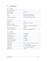
Wire the recorder analog channels. The analog channels will accept a maximum wire size of
12AWG. The terminal block screws are #6. The maximum input to a voltage channel is 440VAC.
The maximum continuous current thru a current channel is 15Amps.
Summary of Contents for APP-601
Page 1: ...APP 601 Recorder Operating Manual...
Page 15: ...Introduction 1 1 1 Introduction...
Page 18: ...2 1 2 Specifications...
Page 25: ...Installation Overview 3 1 3 Installation Overview...
Page 38: ...Hardware 4 1 4 Hardware...
Page 61: ...Installing the Recorder Software 5 1 5 Installing the Recorder Software...
Page 67: ...Using the APP Recorder 6 1 6 Using the APP Recorder...
Page 117: ...Using the APP Recorder 6 51...
Page 124: ...Using the APP Driver 7 1 7 Using the APP Driver...
Page 128: ...Using the OScope 8 1 8 Using the OScope...


