background image


vii 

Contents 

Contents ........................................................................................................................................................ vii


Table of Figures ............................................................................................................................................ xii


Table of Tables ............................................................................................................................................ xiv


1.


Introduction ........................................................................................................................................ 1-1


1.1


Overview ....................................................................................................................................... 1-2


1.2


History ........................................................................................................................................... 1-2


1.3


Features ......................................................................................................................................... 1-2


1.4


Functions ....................................................................................................................................... 1-3


2.


Specifications ..................................................................................................................................... 2-1


2.1


Analog Inputs ................................................................................................................................ 2-2


2.1.1


Voltage ................................................................................................................................ 2-2


2.1.2


Current ................................................................................................................................. 2-2


2.1.3


General ................................................................................................................................ 2-2


2.2


Event Inputs .................................................................................................................................. 2-3


2.3


Power Supply ................................................................................................................................ 2-3


2.4


Status Relays ................................................................................................................................. 2-4


2.5


Time Synchronization ................................................................................................................... 2-4


2.6


Communications ........................................................................................................................... 2-5


2.7


System Computer .......................................................................................................................... 2-5


2.7.1


Choice #1 APP-601 Computer Chassis ............................................................................... 2-5


2.7.2


Choice #2 APP-501 Computer Chassis ............................................................................... 2-6


2.8


Ethernet Switch ............................................................................................................................. 2-7


2.9


Enclosures ..................................................................................................................................... 2-7


2.10


Environment ............................................................................................................................. 2-7


2.11


Approvals ................................................................................................................................. 2-7


3.


Installation Overview ......................................................................................................................... 3-1


3.1


Installation Types .......................................................................................................................... 3-2


3.2


Completing a Centralized Installation ........................................................................................... 3-3


3.3


Completing a Distributed Installation ........................................................................................... 3-7


3.4


Completing a Turn-Key Installation............................................................................................ 3-10


3.5


Basic Connection Diagram.......................................................................................................... 3-12


4.


Hardware ............................................................................................................................................ 4-1


4.1


Available Computer Control Chassis ............................................................................................ 4-2


4.2


Major Duties of the Computer Control Chassis ............................................................................ 4-2


4.3


APP-601 Computer Control Chassis ............................................................................................. 4-2


Summary of Contents for APP-601

Page 1: ...APP 601 Recorder Operating Manual...

Page 2: ...trademarks or registered trademarks of their respective companies Warranty The material contained in this document is provided as is and is subject to being changed without notice in future editions F...

Page 3: ...ceive contains more than one language version of the Software and or multiple Software titles you are only licensed for one language version per Software title contained on the media and you may not t...

Page 4: ...ll APP Engineering Inc liability exceed the purchase price of the software The disclaimer and limitations set forth above will apply regardless of whether you accept the software U S Government Restri...

Page 5: ...aware of the hazards involved should install open any doors remove any covers or disconnect the instrument APP 601 Recorder Disconnect power before attempting any service or maintenance WARNING Fuse F...

Page 6: ...power to this instrument If the instrument includes a three prong AC power cord ensure that your power receptacle is properly earth grounded WARNING Two Person Rule Do not service or adjust equipment...

Page 7: ...7 System Computer 2 5 2 7 1 Choice 1 APP 601 Computer Chassis 2 5 2 7 2 Choice 2 APP 501 Computer Chassis 2 6 2 8 Ethernet Switch 2 7 2 9 Enclosures 2 7 2 10 Environment 2 7 2 11 Approvals 2 7 3 Insta...

Page 8: ...ction 5 2 5 2 Program Installation and Quick Start Settings 5 2 5 3 Startup and Running the APP Monitor 5 5 6 Using the APP Recorder 6 1 6 1 Introduction 6 2 6 2 APP Recorder Program Functions 6 2 6 3...

Page 9: ...ClearView 6 32 6 10 1 Connecting to ClearView 6 32 6 10 2 Disconnecting from ClearView 6 32 6 10 3 Viewing the Connection Status Window 6 32 6 10 4 Choosing a Modem 6 33 6 10 5 Setting the Network Por...

Page 10: ...Measurement Unit PMU 6 53 6 15 Viewing the Help and About Information 6 57 7 Using the APP Driver 7 1 7 1 Introduction to the APP Driver 7 2 7 2 Viewing the APP Recorder Driver Window 7 2 7 3 Reinitia...

Page 11: ...Channel at a time 8 10 8 10 Calibrating Slope Performing an External Calibration 8 10 9 Other Information 9 1 9 1 Time Quality 9 2 9 2 Recommended Maintenance and Calibration 9 3 9 2 1 Performance bas...

Page 12: ...ger Wiring 3 DFR Example 4 15 Figure 13 APP 601 Data Chassis 3D View 4 19 Figure 14 APP 601 Data Chassis Front View 4 20 Figure 15 APP 601 Data Chassis Rear View 4 20 Figure 16 Recorder Configuration...

Page 13: ...Menu Window 6 44 Figure 48 Windows Logon Startup 6 44 Figure 49 Network Path Logon 6 45 Figure 50 DNP 3 Modbus Configuration Window DNP 3 6 46 Figure 51 DNP 3 Modbus Configuration Window Modbus 6 48...

Page 14: ...4 23 Table 9 Values on the SER Report Tab 6 5 Table 10 Configuring Automatic Tasks Options in the Call Master List 6 14 Table 11 Configuring Automatic Tasks Options in the Print List 6 16 Table 12 Def...

Page 15: ...Introduction 1 1 1 Introduction...

Page 16: ...trol chassis choice for the APP 601 recorder system The APP 601 recorder can be purchased with either of the following chassis configurations APP 601 Computer Chassis and APP 601 Data Chassis APP 501...

Page 17: ...ransient Oscillography Extended Oscillography Extended RMS Root Mean Square Continuous Oscillography Continuous RMS Continuous Frequency Continuous Phasor Trending RMS Frequency Sequence of Events PMU...

Page 18: ...2 1 2 Specifications...

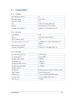
Page 19: ...or 2 seconds 250A RMS for 0 5 seconds Max current not to exceed 250A Accuracy un calibrated Typical 0 61 of Reading Max 1 0 2 1 3 General Ch to Ch phase angle error 0 004 degrees Cut off frequency 3db...

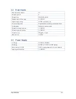
Page 20: ...tact configuration Programmable normally open normally closed Configuration Isolated or common return Channel to channel isolation 3500VDC Channel to ground isolation 3500VDC Connector type Pluggable...

Page 21: ...le alarms to Power Online Continuous Record and Cross Trigger Power On line Off line Clock sync loss Disk Full Master Communication error Chassis Communication error Transient Record Disturbance Recor...

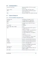
Page 22: ...500GB Min External HDD CDRW DVDRW Option Ports 2x Programmable RS232 422 485 Com1 2 2x RS 232 Com3 4 2x Ethernet 1 for DSP 1 for LAN Intel 82574 1x Ethernet Spare Realtek RT8111C 5x USB2 4 on back pa...

Page 23: ...mpact Flash CF Green When the CF is operating the LED flashes 2 7 2 Choice 2 APP 501 Computer Chassis Operating system XP Professional Windows 7 10 or Linux Ubuntu Processor Intel Duo Core Minimum RAM...

Page 24: ...0 Environment Operating temperature 5 to 55 C Standard 25 to 70 with 601 Computer Chassis and Extended Range HDD or SSD Storage temperature 40 to 70 C Operating relative humidity 0 to 95 non condensin...

Page 25: ...Installation Overview 3 1 3 Installation Overview...

Page 26: ...to the system Ethernet switch The chassis should not be greater than 100 meters from the Ethernet switch if straight Ethernet is used Longer distance can be achieved with Ethernet boosters or by usin...

Page 27: ...re 2 APP 501 Computer Control Chassis Front View Figure 3 Data Chassis Front View Chassis can be located in the same panel or distributed in 2 or more panels The installation steps discussed below do...

Page 28: ...Ensure that all circuit board cards are seated properly and the holding screws are tight Open the front panel doors on each chassis and ensure that internal power supplies connectors and computer are...

Page 29: ...the system Each chassis has one Ethernet RJ45 connector On the Data chassis this connector is located on the DSP IRIG circuit board On the Computer Control chassis it is simply located on the back pan...

Page 30: ...onal APP 601 Monitor and Keyboard chassis for the APP 601 Computer Control Chassis open the hinged front panel door and pull out the monitor and keyboard 22 Carefully and with great prior inspection a...

Page 31: ...c converters or Ethernet extenders were purchased with the instruments all Data chassis should be installed within 100 meters 328 feet of the Ethernet switch 7 Ensure that all circuit board cards are...

Page 32: ...in the Point Assignment Record must be set to reflect the input type Unless a satellite controlled clock is purchased with the system an IRIG B coax cable is not provided The Chassis to chassis 1PPS s...

Page 33: ...from a DSP circuit board to the Computer chassis RS232 connector or to your laptop running APP ClearView With caution power up the Data Chassis and Computer chassis The APP Recorder program should au...

Page 34: ...Record was received prior to shipment the factory has already made the correct jumper settings 7 Wire the analog channel terminal blocks field side The maximum input to a voltage channel is 440VAC Th...

Page 35: ...nd Keyboard chassis for the APP 601 Computer Control Chassis open the hinged front panel door and pull out the monitor and keyboard 14 Carefully and with great prior inspection and thought turn on you...

Page 36: ...R DIGITAL 1 2 3 4 5 6 7 8 DIGITAL 1 2 3 4 5 6 7 8 125VDC 125VDC RET ON OFF 12VDC OUT 12VDC RET OUT POWER 1 2 3 4 5 6 DSP ANALOG ANALOG ANALOG ANALOG ANALOG ANALOG 19 21 22 24 25 27 28 30 31 33 34 36 1...

Page 37: ...4 5 6 7 8 TB2 1 9 2 3 4 5 6 7 8 TB3 1 9 2 3 4 5 6 7 8 TB4 1 9 2 3 4 5 6 7 8 TB5 1 9 2 3 4 5 6 7 8 TB6 1 9 2 3 4 5 6 7 8 TB1 1 9 2 3 4 5 6 7 8 1 9 2 3 4 5 6 7 8 TB10 1 9 1 16 2 3 4 5 6 7 8 2 3 4 5 6 7...

Page 38: ...Hardware 4 1 4 Hardware...

Page 39: ...supply 12V 50Watt power supply and rear slide in power supply circuit board The single board computer with compact flash and 2 5 hard drive USB modem and a connector circuit board are all mounted on a...

Page 40: ...the BIOS also contains codes and various advanced features applied to the serial controller The BIOS setup program includes menus for configuring settings and enabling computer board features To enter...

Page 41: ...in 2 of CN2 are jumpered and the system restores to default BIOS settings 2 SATA Connector The SATA connector port is used for the hard drive It supports data transfer up to 3 0 Gbits s 300MB s The SA...

Page 42: ...RS 232 Com3 4 2x Ethernet 1 for DSP 1 for LAN Intel 82574 1x Ethernet Spare Realtek RT8111C 5x USB2 4 on back panel 1 on front panel 2x eSATA 2x PS2 Keyboard Mouse 1x VGA 1x Modem 56K 1x Sound 1x MIC...

Page 43: ...Hardware 4 6 Figure 6 APP 601 Computer Control Chassis Front View Figure 7 APP 601 Computer Control Chassis Rear View...

Page 44: ...is removed to allow for automatic power toggle during the automatic reboot processes Also the D series laptops have their power buttons shorted and the E series laptops have the BIOS configured to all...

Page 45: ...on Operating system XP Professional or Windows 7 or 10 or Linux Ubuntu Processor Intel Core i5 2 6GHz RAM 2GB DDR Minimum SSD Option Internal HDD 500GB Min External HDD Option DVDRW Yes Ports 1 RS232...

Page 46: ...Hardware 4 9 Figure 9 APP 501 Computer Control Chassis Front View Figure 10 APP 501 Computer Control Chassis Rear view...

Page 47: ...he sum total does not exceed ten Functions and features of the Data Chassis circuit boards are discussed below 4 5 1 Power Supply Circuit Board Fuses the input power 2Amp 250V 3AG Slo Blo Glass Cartri...

Page 48: ...t board and on to various boards that plug into the mid plane 4 5 3 12VDC Power Supply Module The output of this module is 12VDC 100W The module includes over load over voltage and over temperature pr...

Page 49: ...E standard that an error greater than 1ms has occurred The relay will stay energized until a synchronized condition is reestablished Most users will set this contact as normally open Chassis to Chassi...

Page 50: ...hannel The relay will energize if the measured value of the analog channel goes to maximum negative indicating a failed channel Note Even though this alarm is not mapped to an alarm output if a failed...

Page 51: ...low sample unique addressing scheme CAUTION If you are adding Cross Trigger to existing DFRs you may have to re address the Computer Unit and DSP IP addresses to eliminate any duplicates when connecti...

Page 52: ...gative terminals together and connect to station battery return DC return Event channels are scanned at the same rate as the analog channels The scan rate is user programmable and includes choices of...

Page 53: ...on back of DSP board under the JP2 If the DSP IRIG board loses the 1PPS signal from the satellite controlled clock the DSP IC no longer receives a 1PPS interrupt signal In this case the DSP will rely...

Page 54: ...cates that an IRIG B signal has been connected to the DSP circuit board the 1PPS signal is part of the IRIG B signal External 1PPS indicates the DSP circuit board is receiving a 1PPS signal from anoth...

Page 55: ...en V C voltage and common For a current channel the input should be wired between I C current and common WARNING The maximum input voltage for a voltage channel is 440VAC The maximum continuous curren...

Page 56: ...with the system modem or network card The LED will remain illuminated until the problem has been fixed CHASSIS CHASSIS COMM ERROR Red Illuminates if any data acquisition chassis stops communicating wi...

Page 57: ...Hardware 4 20 Figure 14 APP 601 Data Chassis Front View Figure 15 APP 601 Data Chassis Rear View Blank Panels Shown in Slots 5 6 Analog or Event Board can be inserted...

Page 58: ...ast storm control to prevent excess broadcasts from degrading network performance To aid in troubleshooting each port LED is lit solid if a valid link exists to an attached device flashes to show acti...

Page 59: ...must CAUTION The Ethernet Switch is used for the DSP network only The users company LAN WAN connects to a RJ45 connector labeled LAN Enet on the Computer chassis rear panel CAUTION From time to time...

Page 60: ...ress Value Computer Control Chassis Typical IP Address 195 168 3 220 Subnet Mask 255 255 255 0 1st Data Chassis Typical Ethernet Address 1 35 69 86 120 1 IP Address 195 168 3 1 Subnet Mask 255 255 255...

Page 61: ...Installing the Recorder Software 5 1 5 Installing the Recorder Software...

Page 62: ...ion of the APP Recorder Program should not be necessary It will be installed and setup at the factory The following installation steps are provided in the event a future software load is required To I...

Page 63: ...yed in its Fault Summary Table Settings under the Automatic Tasks or Allowed IPs tab are not required for recorder startup and will be discussed in a later section 13 Click Save in the upper left hand...

Page 64: ...so be placed in the box by simply selecting the box and typing the letter E Note Slot 7 is always reserved for the DSP circuit board Slot 12 is always reserved for the alarm output circuit board and s...

Page 65: ...he system is not synchronized with a satellite controlled clock you will hear the CLK SYNC LOSS relay click after approximately 1 minutes The system is now operational and the complete Point Assignmen...

Page 66: ...want the APP Monitor to automatically start when you run the APP Recorder If yes then select the APP Monitor check box If no then skip to the next step Note If APP Monitor is shut down using Task Man...

Page 67: ...Using the APP Recorder 6 1 6 Using the APP Recorder...

Page 68: ...data from the DSP circuit boards and writes that data in path location of C D APP Recorder Data OsclgrData This data is used when the analysis software is requesting a time slice of continuous oscillo...

Page 69: ...g section provides a quick look at RMS values for all the analog channels event status trigger status and the sequence of event logs You can use the tabs in this section to view different types of inf...

Page 70: ...bleshooting tool Events SER Tab Figure 23 Events SER Tab The Events SER tab shows the configuration of the event SER If you highlight any of the row s and then right click a pop up menu will display t...

Page 71: ...ral Settings tab in the Point Assignment Record you can specify the threshold of time for allowable state changes in other words the acceptable amount of time between state changes If the SER channel...

Page 72: ...t Summary Report Recent Fault Summary Report with Graph 6 5 1 Selecting and Configuring the Printer Before you print select and configure the printer that you want to use To Select and Configure the P...

Page 73: ...ng the APP Recorder You can exit the APP Recorder for maintenance or troubleshooting purposes When you exit the APP Recorder the APP Driver is automatically exited as well If you have set an administr...

Page 74: ...on Settings You can configure the following types of settings for the APP Recorder Main configuration settings Automatic tasks Allowed IPs 6 7 3 Configuring the Main Configuration Settings Main config...

Page 75: ...quentially 3 Company Name field enter any name you would like This name will appear at the top of the APP Recorder Program main page At the factory the name of the company who purchased the system is...

Page 76: ...hang up command When this is done both programs are aware of the disconnect request and can properly close down communications However it is possible for a communication path to be cut without notice...

Page 77: ...only the modem and then click Next 6 Select Do not allow virtual private connections and then click Next 7 Under User Permissions select the users and then click Next 8 Under Networking Software check...

Page 78: ...is To setup Dial up networking with Windows 7 or above please contact APP Engineering support at 317 536 5300 6 7 5 Configuring Automatic Tasks The APP Recorder can perform a variety of automatic task...

Page 79: ...ndow Automatic Tasks Tab 6 7 7 Configuring Automatic Tasks that Occur when a Fault Arrives Call Master You can configure whether or not the APP Recorder calls the master station and what type of data...

Page 80: ...all of the boxes are unchecked then all of the types of data will be sent A Fault Summary File Only when certain conditions occur Yes if logic true Send FSum Only Max Faults in FSum box on the Main ta...

Page 81: ...polling cycle 6 Do an Auto Test Run if no fault occurs in a week will initiate a test run if there has been no faults recorded in the past week This is to provide a way to ensure the recorder is func...

Page 82: ...cur Yes if logic true Print FSum and Data Logic OR 1 AND box Data means these only check boxes A Fault Summary File always and associated data sometimes Always print a Fault Summary Report but Print a...

Page 83: ...am printed YScale Channel Full Scale Optimized unit cm Prints a volts cm or amps cm scale to the right hand side of each oscillogram printed The value is based on the full scale setting in the Point A...

Page 84: ...splayed page In the Digital Channel Format list select how the trigger line should appear whether it is normal or abnormal Sequence Of Events Triggers Line on Abnormal This selection only prints the e...

Page 85: ...Using the APP Recorder 6 19 Figure 29 Default Report Format Figure 30 Report with Spread digital among graphs checked...

Page 86: ...or oscillogram page 14 In the Annotation Text Size box enter the font size for any annotations that are added to a waveform or oscillogram page 15 Click OK 6 7 10 Configuring Email Settings You can co...

Page 87: ...your network administrator to obtain values for the Outgoing Mail SMTP Port and User ID fields 7 Do you want the APP Recorder to automatically email a summary of every fault each time the master stati...

Page 88: ...end Fault Summary is also checked 9 From the menu bar click Save At this point you have completed configuring e mail settings It is a good idea to send a test e mail to ensure that messages will be se...

Page 89: ...y generated transient fault record to a host directory To Configure FTP Settings 1 Open the Recorder Configuration window and open the Automatic Tasks tab 2 Select the FTP check box Note You must set...

Page 90: ...rectory per hour Specify a limiter here to stop the host directory from being inundated with data in the event that the APP Recorder has an unexpected runaway tripping event Note You can reset the cou...

Page 91: ...ed In the Remote Dir field type the path to the remote directory that is located on the host site to which the transient records will be sent for example storage Note The backward slash may need to be...

Page 92: ...olean Logic Filter Variables and Entries Entry Description 0 False nothing will pass filter 1 True everything passes filter Blank Nothing Entered True everything passes filter T1 T2 T3 Represents Anal...

Page 93: ...file appears in the remote directory that you specified on the Directory tab To Stop the Automatic Retry Attempts If the transfer fails and you wish to stop the automatic retries click Abort To Clear...

Page 94: ...s the Master Phone List when Alarms Occur 1 Open the Recorder Configuration window and open the Automatic Tasks tab 2 Under the When Alarms Occurred Do section do one of the following If you want the...

Page 95: ...the Add button For information on configuring DialNet see Setting Up Dial up Networking If no skip to the next step 4 By default the first entry that you make is selected as indicated by the X in the...

Page 96: ...to be set to Yes If a failure occurs it will cause a Master Comm Error You must map that alarm in the Point Assignment Record General Settings Recorder Setup tab to have a hard alarm displayed 6 7 18...

Page 97: ...e APP Recorder you can access the Point Assignment Record from the Edit menu of the APP Recorder window For complete details on how to create and edit the Point Assignment Record see the APP ClearView...

Page 98: ...ct to ClearView Note The APP ClearView master station program will not receive a call unless it is set to monitor incoming calls 6 10 2 Disconnecting from ClearView You can manually break the connecti...

Page 99: ...ust settings during troubleshooting To Choose the Modem 1 In the APP Recorder window from the Connect menu point to Modem and then click Choose Modem The Choose Modem dialog box appears Figure 39 Choo...

Page 100: ...Files You can use trace files to help during troubleshooting There is a separate trace file for the APP Recorder and the APP Driver Trace files include Tracexxx wri Driver Trace File CTracexxx wri Co...

Page 101: ...ate a manual diagnostic test against the APP Recorder and view the results Note You can also run a diagnostic test from within the APP Driver window and from the master station To Run a Diagnostic Tes...

Page 102: ...ription along with either an M or an A M indicates that the channel has been stopped manually via the Point Assignment Record A indicates that the channel stopped automatically 6 11 4 Performing a Tes...

Page 103: ...h fault record is created the Fault Identification number or FID is incremented by one If the extended recording feature is enabled in the Point Assignment Record General Settings tab Sampling tab a s...

Page 104: ...or will restart APP Recorder within 60 seconds CAUTION The re initialize command will take the APP Recorder offline for a few moments 6 11 9 Rebooting the APP Recorder Program You can re boot the APP...

Page 105: ...erve Memory A Warning message appears 4 Click Yes 5 To check if the reserve memory process is finished look at the APP Recorder trace file In this file the message Begin Reserve Memory appears when th...

Page 106: ...ximum circular buffer however 15 days is more practical and depends on the number of analog channels and hard drive size Figure 43 Continuous Recording Menu 6 12 1 Viewing the Continuous Recording Sta...

Page 107: ...Data 1 In the APP Recorder window from the Continuous Recording menu point to Frequency and then click Save Freq Data MAX File Size Enter the file size in Megabytes for the file size you wish to allo...

Page 108: ...APP Recorder window from the Continuous Recording menu point to Frequency and then click Save Freq Data 2 Complete the entry fields 3 Trend Check Box checking the Trend box will create a Frequency Co...

Page 109: ...in minutes typically 1 minute is used At the bottom of the window you can see the expected file size and the effect of interval minutes selected If no then skip to the next step 4 Click the OK button...

Page 110: ...1 Startup and Running the APP Monitor APP Recorder can be set up to automatically start when the computer restarts and using APP Monitor to automatically start if APP Recorder is shutdown When APP Mo...

Page 111: ...automatically start when you run the APP Recorder as an application Note Speedfan is required for the PC Health Alarm to function due to Hard Drive Temperature and is required for monitoring Drives wi...

Page 112: ...ceived is located in the file RxxDnp3 txt in setup folder of the recorder This file is generated by the APP 601 Recorder automatically DNP 3 Modbus Prerequisites You can configure a DNP3 or Modbus out...

Page 113: ...e port number 5 Sending analog floating points on Class 0 Check this box if you want to send values converted to Floating Point instead of HEX values to the RTU Otherwise for the RTU to receive HEX le...

Page 114: ...col If you are using a RS232 port select RS232 then from the Baud Rate list select a baud rate that will work with your RTU If you are using a TCP IP select Network then enter the port number The stan...

Page 115: ...four options for adding Channels or lines to the mapping Analog Channels for RMS Analog Channels for Frequency Analog Channels for Phase Lines for Fault Location Each record will be labeled with a nu...

Page 116: ...irect route is to access the Email Settings window directly from the Tools menu To Show the Email Settings Window In the APP Recorder window from the Tools menu click Show Email Window The Email Setti...

Page 117: ...Using the APP Recorder 6 51...

Page 118: ...255 255 0 1st Data Chassis Typical Ethernet Address 1 35 69 86 120 2 IP Address 195 168 3 2 Subnet Mask 255 255 255 0 Default Gateway 195 168 3 220 2nd Data Chassis Typical Ethernet Address 1 35 69 8...

Page 119: ...eters to the APP Recorder or to a communications device switch Auto Neg is the default setting and is used when connected directly to the APP Recorder computer or to an APP Engineering supplied switch...

Page 120: ...b 4 Select the PMU check box 5 From the menu bar click Save A message window appears confirming the save operation 6 Click the OK button 7 Click the Analog Channels tab For more information on how to...

Page 121: ...What to Send select the appropriate channels for Va Vb Vc Ia Ib and Ic To do this click the corresponding pull down menu select the desired channel Note The analog channels that appear here are config...

Page 122: ...Event check box a list of events appears for you to choose which events to include Select the channels and click OK 11 Plus Triggers check box allows you to add trigger channels to the PMU to include...

Page 123: ...icking Close does not automatically save the settings Remember to click Update 6 15 Viewing the Help and About Information You can view the online help for the APP Recorder The About information inclu...

Page 124: ...Using the APP Driver 7 1 7 Using the APP Driver...

Page 125: ...1PPS signal for all the DSP boards The times are updated every 30 seconds If multiple times are displayed meaning that there are two or more DSP boards they should be the same Packet Ex If extended re...

Page 126: ...is still running in the background 7 5 Doing a Diagnosis A diagnosis provides a general overview of the health of the Driver To Do a Diagnosis In the APP Driver window from the menu bar click Do Diag...

Page 127: ...indow includes the driver version and factory contact information Note If the help files do not answer your question s please do not hesitate to contact APP Engineering Inc at 317 536 5300 To View the...

Page 128: ...Using the OScope 8 1 8 Using the OScope...

Page 129: ...the OScope window is open To View the OScope Window 1 Do one of the following From the APP Recorder window from the File menu click Show OScope From the APP Driver window from the menu bar click OSco...

Page 130: ...a normal state If the box is red the channel is in an abnormal state Figure 59 Oscope Window Event Status Tab 8 2 3 Triggers Tab The Triggers tab indicates which analog channels are in a trip conditio...

Page 131: ...an absolute full scale value based on the finite hardware choices The absolute full scale is the amplitude at which the input signal will clip Optimize If you select Optimize the Y axis will automati...

Page 132: ...he APP Recorder returns to its normal online status To Exit the OScope Window In the APP OScope window from the File menu click Exit 8 5 Editing the Point Assignment Record You can edit the Point Assi...

Page 133: ...ord General Settings tab Sampling tab packet transfers or data flow from the DSP circuit boards to the computer hard drive can be seen here Recovery Extended If the extended recording feature is enabl...

Page 134: ...message M indicates that the channel has been stopped manually via the Point Assignment Record A indicates that the channel stopped automatically Note If an SER channel frequently changes its state y...

Page 135: ...ch channel offset by stepping through the channels in the Show Analog Channels section Note After calibrating click Run to restart the OScope function To Un Calibrate All Offsets To reverse the calibr...

Page 136: ...econds power will automatically return and the system will restart It takes approximately 1 minute and 30 seconds for the system to return to an online state To Reboot the Driver In the APP OScope win...

Page 137: ...wn arrows to enter the analog channel number to be calibrated Holding the up or down arrow will scroll quickly and then click the corresponding OK button Figure 63 Show Analog Channels Group 2 Under C...

Page 138: ...nnel number to be calibrated and then click the corresponding OK button 3 In the External Calibration Slope group in the At Secondary box enter your known accurate secondary input calibration voltage...

Page 139: ...Other Information 9 1 9 Other Information...

Page 140: ...44 quality indicator codes IMPORTANT APP 601 clock accuracy alignment with the 1PPS is 0 6 sec with an un modulated IRIG B input The accuracy with a modulated IRIG B input is 1msec If the satellite co...

Page 141: ...r each APP Recorder see Clearview Manual for more on setting up Auto Polling The following procedure explains how to complete the minimum recommended performance based maintenance procedure To Complet...

Page 142: ...og channels once every 5 years See calibrating DC offest and calibrating Slope 9 3 Recommended Setup for MW Channels Using 4ma 20ma Transducer To Complete the Recommended Setup for MW Channels 1 Calcu...

Page 143: ...rder to display proper primary values 2 In the Point Assignment Record for this analog channel enter q MVar for the Channel Type enter 349 650 for the CT PT value and enter 5 for the Full Scale value...

Page 144: ...ch is the shunt value that needs to be used in order to display proper values 2 In the Point Assignment Record for this analog channel enter C Adc for the Channel Type Enter 1 for the CT PT value ente...

Page 145: ...e a few minutes for the recorder to go on line It is possible for the APP Recorder program to start up and display information but the front panel lights indicate an off line status In this case do no...

Page 146: ...own the APP Recorder program it will remain off 3 To setup the APP Recorder program so that it automatically starts after being closed go to the APP Recorder folder typically on the root C drive and d...

Reviews: