
HEADQUARTERS: Anderson Power Products®, 13 Pratts Junction Road, Sterling, MA 01564-2305 USA T:978-422-3600 F:978-422-3700
EUROPE: Anderson Power Products® Ltd., Unit 3, Europa Court, Europa Boulevard, Westbrook, Warrington, Cheshire, WA5 7TN United Kingdom T: +44 (0) 1925 428390 F: +44 (0) 1925 520203
ASIA / PACIFIC: IDEAL Anderson Asia Pacific Ltd., Unit 922-928 Topsail Plaza, 11 On Sum Street, Shatin N.T., Hong Kong T:+(852) 2636 0836 F:+(852) 2635 9036
CHINA: IDEAL Anderson Technologies (Shenzhen) Ltd., Block A8 Tantou Western Industrial Park, Songgang Baoan District, Shenzhen, PR. China 518105 T: +(86) 755 2768 2118 F: +(86) 755 2768 2218
TAIWAN: IDEAL Anderson Asia Pacific Ltd., Taiwan Branch, 4F.-2, No.116, Dadun 20th St., Situn District, Taichung City 407, Taiwan (R.O.C.) T: +(886) 4 2310 6451 F:+(886) 4 2310 6460
www.andersonpower.com
14820 1S6530 ASM-6PEXSPREC REV01
Extreme Power SPEC Pak
™
Receptacle
Page 2
PATENTS AND TRADEMARKS This product is Patent Pending.
Gasket
APP
Logo
Pin 2 - Relative
Pin 1
Pin 3
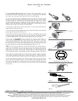
5. If using Powerpole 15/45 insert holder: block Powerpole
®
15/45 housings together, then insert
Powerpole block into 15/45 holder (See Figure 6a). Line up holes in Powerpole block with retaining pin
hole in holder. Insert retaining pin (See Figure 6b) until flush to complete assembly.
The PP15/45 holder insert should be installed from the front as shown in (See Figure 7a). Install
retaining pins in order shown relative to the PP15/45 holder insert (See Figure 7b). The short retaining
pin must be installed in the center hole first and be fully recessed into the Powerpole block. It should
not make contact with the large outer Powerpole Holder. Next install a long retaining pin into the hole
adjacent to the PP15/45 holder insert. Install the last long retaining pin. All long retaining pins should be
installed so they are flush with the large outer Powerpole Holder.
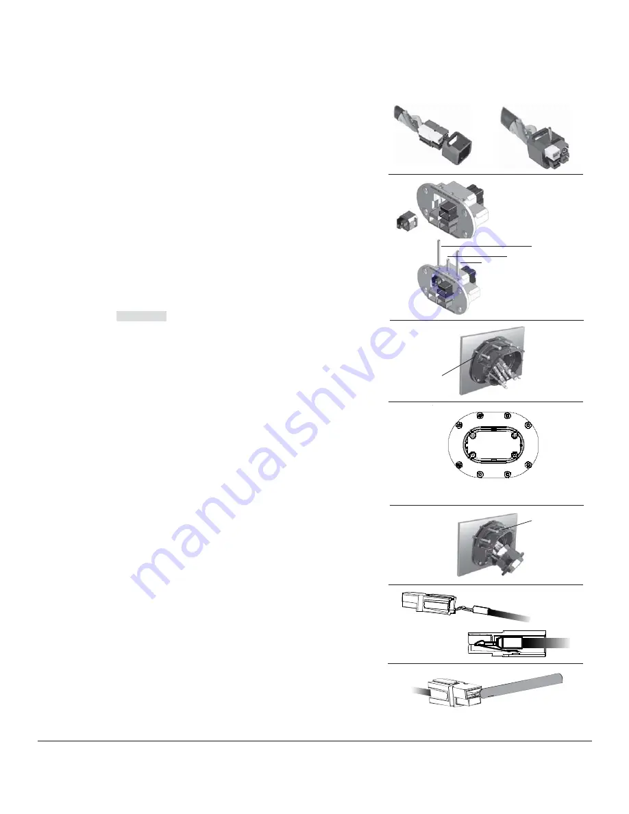
6. Prepare panel by cleaning and drying the panel surface. To ensure proper sealing, the panel
flatness should be 0.002 inches per inch.
7. Slide Panel Mount Gasket and Receptacle Shell onto wires. Panel Mount Gasket should be between
panel and rear of Receptacle Shell (See Figure 8).
8. Attach SPEC Pak Receptacle to panel with eight, #6 screws (not included). Make sure the surface
of the panel contacting the sealing gasket is clean and dry to ensure an IP68 seal. Screws should be tightened
in an opposite, alternating manner, to provide even torque and sealing to the panel. (See Figure 9).
9. Position holder so
Receptacle
is facing up and APP Logo on Receptacle Shell is facing up.
Install contacts into Powerpole Housing(s). Position contacts as shown (See Figure 10). Push contact
and wire into Powerpole Housing so contact snaps into place. The contact will slip under the internal
barrier and snap over the end of the internal retaining spring. Repeat until all wires and contacts have
been firmly locked into their respective Powerpole Housings (See Figure 11a & 11b).
NOTE: To insert or remove a contact from a PP15/45 Powerpole Housing, use Anderson insertion /
extraction Tool P/N: 111038G20. Place one of the forward prongs of the tool between the contact and
spring. Using a rotary motion, continue rotation while pulling on the wire until the prong causes
disengagement of the contact from the retention spring (See Figure 12). Withdraw contact from the
rear of the Powerpole Housing. Reinstall contact into correct Powerpole Housing per Step 9 above.
To remove contact from Powerpole PP75 to PP180, use small, flat blade screwdriver to depress
contact retention spring below retention feature of contact (See Figure 12). Withdraw contact from
the rear of the Powerpole Housing. Reinstall contact into correct Powerpole Housing per Step 9 above.
10. Press Powerpole Holder into Receptacle Shell until 4 screw holes align. Holder and shell are
keyed so they will only go together one way. Insert four M5x25mm hex screws (supplied), using a
3mm hex bit, torque screws to 3-3.2 NM (25-26.5 in-lbs). The screw head should be recessed into
the countersink. CAUTION: Do not torque beyond 3.2 N-M (26.5 in-lbs) as this may cause damage
to the connector.
Figure 6a Figure 6b
Figure 7a
Figure 7b
Figure 8
Figure 9
Figure 10
Figure 11
Figure 12
1
2
3
4
5
6
7
8
Torque bolts to 26 - 30 in-Lbf (3 - 3.4N)


