HEADQUARTERS:
Anderson Power Products®, 13 Pratts Junction Road, Sterling, MA 01564-2305 USA T:978-422-3600 F:978-422-3700
EUROPE:
Anderson Power Products® Ltd., Unit 3, Europa Court, Europa Boulevard, Westbrook, Warrington, Cheshire, WA5 7TN United Kingdom T: +44 (0) 1925 428390 F: +44 (0) 1925 520203
ASIA / PACIFIC:
IDEAL Anderson Asia Pacific Ltd., Unit 922-928 Topsail Plaza, 11 On Sum Street, Shatin N.T., Hong Kong T:+(852) 2636 0836 F:+(852) 2635 9036
CHINA:
IDEAL Anderson Technologies (Shenzhen) Ltd., Block A8 Tantou Western Industrial Park, Songgang Baoan District, Shenzhen, PR. China 518105 T: +(86) 755 2768 2118 F: +(86) 755 2768 2218
TAIWAN:
IDEAL Anderson Asia Pacific Ltd., Taiwan Branch, 4F.-2, No.116, Dadun 20th St., Situn District, Taichung City 407, Taiwan (R.O.C.) T: +(886) 4 2310 6451 F:+(886) 4 2310 6460
www.andersonpower.com
SPEC Pak
™
High Power Panel Mount Receptacle
Page 2
PATENTS AND TRADEMARKS 14938 1S6555 REV 01
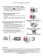
Step 4 Insert Powerpole
®
block into Powerpole
®
Holder:
• With Hood up, slide Powerpole
®
block into the holder half marked with on the
right side, aligning the holder posts with the grove in Powerpole
®
holes (See Figure 4)
• Orient the remaining holder half with on the right side (See Figure 4)
• Slide remaining half into the assembly, inserting the holder posts into the Powerpole
®
holes and aligning the tongues and grooves on the holder halves
Step 5 Install Receptacle housing on the panel:
• Clean and dry the panel surface thoroughly
• Orient housing with APP logo facing up
• Sandwich panel mount receptacle gasket between the panel and the receptacle shell
(See Figure 5)
• Secure the panel mount receptacle and gasket to the panel with size #10 or M5
screws (not included) in an alternating manner. Suggested Torque: 15-20 in-lbs (1.7-
2.2 N-M)
Step 6 Install crimped signal contacts into the holder and
crimped power contacts into the connector housings.
• Pull wires through the panel
• Orient the insert holder with the to the right (See Figure 6)
• Snap the crimped signal contacts into the appropriate holes in the back of the holder
halves (See Figure 7). A tactile snap will be felt when contact is latched.
• Insert crimped power contacts into the appropriate Powerpole® housing until the con
-
tact lip snaps over the edge of the spring (See Figure 8)
• Repeat until all power and/or signal contacts have been installed into the housing
Step 7 Install insert holder into the receptacle shell
• Verify that the O-Ring is properly seated in the receptacle shell
• Secure insert holder to the panel mount receptacle by tightening the screws in an
alternating manner. Torque: 13 in-lb (1.4 N-M)
REGISTRATION
“Anderson Power Products”, “APP” are registered U.S. and foreign trademark of Anderson Power Products
®
, 213 Pratts Junction Road, Sterling, MA 01564-2305 USA www.andersonpower.com
Figure 4
Figure 5
Figure 6
Suggested Hood
Orientation for
Receptacle
Groove
Assembled Holder
Pins
Sockets
Latched
Contact
Panel Hardware
Not Included
Flatness
[ 0.002]
0.05
Gasket
Figure 7 Figure 8


