5/6
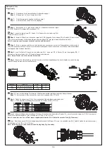
Etape 1 :
Sélectionnez la fiche appropriée dans le tableau de la page 2
Etape 2 :
Dévissez les 3 vis (S) sur le corps de la fiche.
Step 1 :
Select the appropriate plug from the table on page 2
Step 2 :
Unscrew the three screws (S) on the plug body.
FR
GB
Etape 3
: Desserrez les Vis (S) de Pince de câble (FC) et détachez l’anneau de support
de fil (WH), Rondelle (W) et bague de Presse-étoupe (OS).
Step 3 :
Loose the cable clamp (FC) Screws (S) & Remove the wire holder ring (WH),
Washer (W) & onion seal (OS).
FR
GB
Montage de la fiche
Plug assembly
S
S
WH
WH
S
S
OS
OS
W
W
PB
PB
FC
FC
S
S
Etape 6 :
Serrer les vis de câblage (S) entièrement. Utilisation recommandée couple de serrage selon tableau ci-dessous:
Etape 7 :
Fixer le corps de la fiche en vissant les trois vis à un couple de 2 Nm (17.7 lb-in).
Step 6 :
Tighten the wiring screws (S) fully. Use recommended tightening torque as per below chart:
Step 7 :
Fix the plug body by tightening the three screws to a torque of 2 Nm (17.7 lb-in).
FR
GB
Etape 8 : Appuyez le Bague de presse-étoupe (OS) dans le corps de fiche, assemblez la Rondelle (W), vissez l’anneau de support de fil (WH) fermement et
serrez les Vis de pince de câble (S) avec un couple de 1 to 1.5Nm ( 8.8 to 13.3 lb-in).
Note - Assurez-vous que il y a suffisant espace supplémentaire pour les fils à l'intérieur du corps de fiche (fig. Ci-dessous).
Step 8 : Press the onion seal (OS) into the plug body shell, assemble the Washer (W), screw the wire holder ring (WH) tightly & tighten the cable clamp screws
(S) with torque of 1 to 1.5Nm ( 8.8 to 13.3 lb-in)
Note - Ensure that there is some extra wire inside the plug body (Fig. here below).
FR
GB
A
B
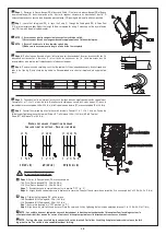
Etape 4 :
Insérez le Câble (C) par l’anneau de support de fil (WH), bague de Presse-étoupe (OS) et Rondelle (W) dans la Fiche
(PB), si nécessaire découpez un couche de la Bague de presse-étoupe (OS) pour égale le diamètre extérieur de câble.
Note - Assurez-vous que les coupes circulaires sont vers côté de terminal.
Etape 5 :
Retirer la gaine du cable afin qu’il reste toujours serré correctement. Inserrez les fils dénudés dans les bornes de la
fiche. Des informations vous sont fournies sur le bouchon d’isolation pour faciliter la connexion. Les tailles de cable recommandées
sont indiquées dans le tableau ci-dessous.
Step 4 :
Insert the Cable (C) through the wire holder ring (WH) , onion seal (OS) & Washer (W) into the plug body (PB), If
necessary cut the layer of onion seal (OS) to match the outer cable diameter
Note - Ensure Circular cuts to face towards terminal side.
Step 5 :
Remove the cable sheathing, such that the cable will still be clamped adequately. Insert stripped wire ends in the plug
terminal. Marking are shown on the insulation cap for
FR
GB
FR
GB
AMPERAGE
WIRE SIZE
A (mm)
B (mm)
16A
2.5 mm² to 4 mm² Flexible
110
17
32A
6 mm² to 10 mm² Flexible
110
17
WH
WH
OS
OS
PB
PB
C
C
S
S
W
W
FC
FC
C
C
FACE A
FACE A
(PLAIN)
(PLAIN)
FACE B
FACE B
(CIRCULAR CUTS)
(CIRCULAR CUTS)
TERMINAL SIDE
TERMINAL SIDE
AMPERAGE
AMPERAGE
WIRE SIZE
WIRE SIZE
TORQUE
TORQUE
16A
16A
2.5 mm²
2.5 mm²
1.5 to 1.7 Nm (13.3 to 15.0 lb-in)
1.5 to 1.7 Nm (13.3 to 15.0 lb-in)
16A
16A
4 mm²
4 mm²
1.5 to 1.7 Nm (13.3 to 15.0 lb-in)
1.5 to 1.7 Nm (13.3 to 15.0 lb-in)
32A
32A
6 mm²
6 mm²
2 to 2.2 Nm (17.7 to 19.5 lb-in)
2 to 2.2 Nm (17.7 to 19.5 lb-in)
32A
32A
10 mm²
10 mm²
1.0 to 1.5 Nm (8.8 to 13.3 lb-in)
1.0 to 1.5 Nm (8.8 to 13.3 lb-in)
WH
WH
S
S
C
C


