background image

Appleton • 1.800.621.1506 • www.appletonelec.com

650483-000 Rev. B 07/15 • Page 7 of 10

INDICATOR LIGHT

RED

BATTERY

12V, 1A MAX

N

L

_

MOUNTING PAN

G

G

N

L

+

+

+

+

_

_

_

_

+

RED

RED

RED

BLACK

BLACK

BLACK

BLACK

LAMP 1

LAMP 2

LAMP 3

LAMP 4

RED

BLACK

BATTERY PACK

LIGHT HEAD 1

LIGHT HEAD 2

LIGHT HEAD 3

LIGHT HEAD 4

+

+

+

+

N

L

BONDING WIRE

AC/DC

ADAPTOR

CONDUIT

GROUND PLATE

AC INPUT

100-277

PUSH-TO-TEST SWITCH
(NC)

UP TO FOUR (4) LIGHT HEADS CAN BE
CONNECTED USING SEPARATE
REMOTE LIGHT BOX(ES)

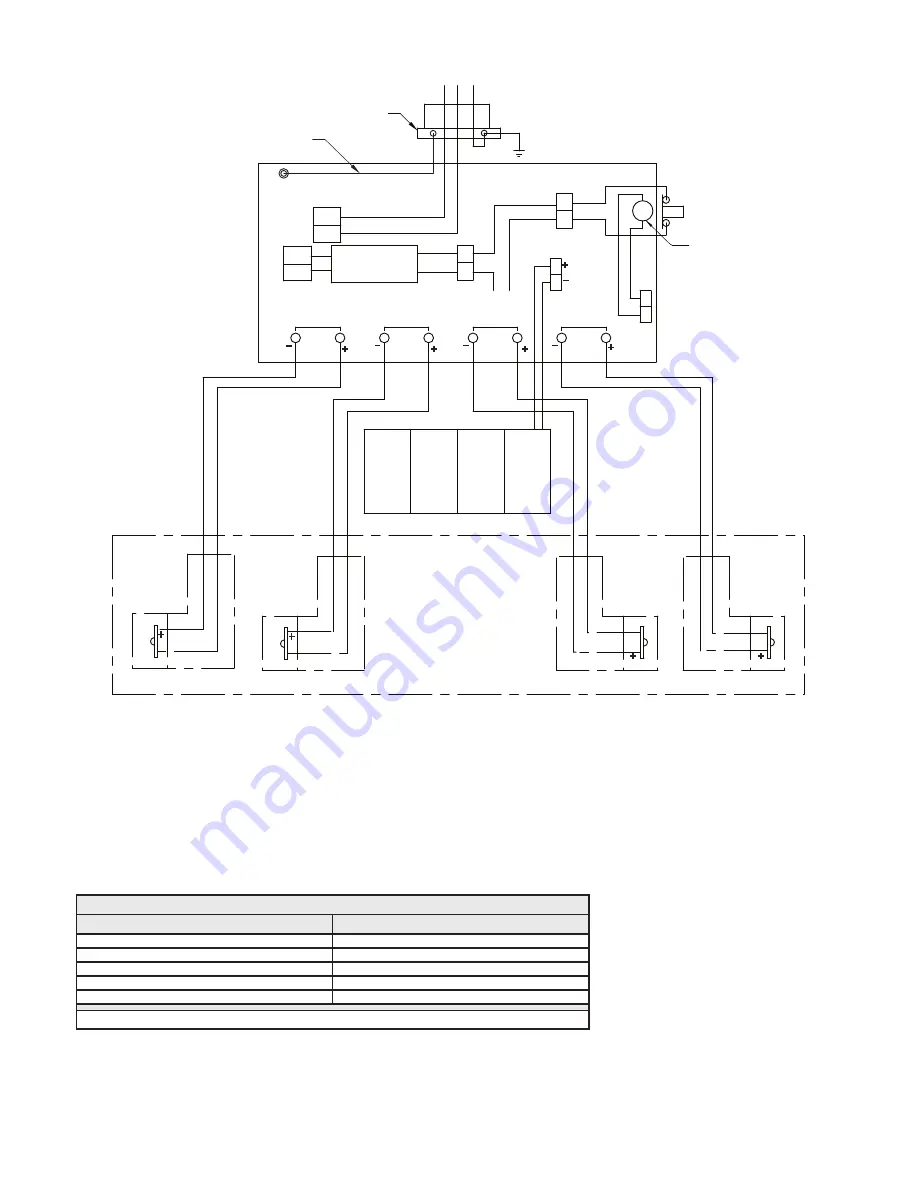
Figure 6: Wiring Diagram for N2LED0T1 Master Unit

6. 

Feed the remote unit wires through the conduit hub to the main unit.

7. 

Connect the additional remote light head wires to the open lamp terminals by following the polarity on the wiring diagram. 

8. 

If applicable, install and connect the remote unit(s) as shown in Figures 7 & 8. Wire sizes are provided in Table 1.  

NOTE:

 The hub must be grounded. After the final conductor routing, use a thread sealant in the conduit-to-hub joint to maintain 

maximum environmental protection.

Table 1: Wire Size for Remote Units*

Maximum Wire Length

Wire Gage

78 ft.

18 AWG

125 ft.

16 AWG

198 ft.

14 AWG

315 ft.

12 AWG

500 ft.

10 AWG

*

Use copper wire between the power supply and the remote lighting system to limit the voltage drop to 5%

Summary of Contents for N2LED Series

Page 1: ...prevent ignition of hazardous atmospheres the area must be free of hazardous vapors before opening the enclosure or servicing the fixture To reduce the possibility of static sparking do not attach metallic parts to the outside of the unit e g metallic screws tags decals etc Do not mount the unit near gas or electric heaters De energize the unit before opening To reduce the risk of electric shock d...

Page 2: ...UR 4 PLACES COVER SCREW INSERT FOUR 4 PLACES LIGHT HEAD CONTACT EIGHT 8 AVAILABLE FOR MAXIMUM FOUR 4 LIGHT HEADS INSTALLER CONNECTS BATTERY TO PCA CONNECTOR PUSH TO TEST SWITCH INTEGRAL PILOT LIGHT 5 75 in 146 mm 7 87 in 200 mm 9 80 in 248 9 mm 7 44 in 189 mm 8 46 in 215 mm 9 00 in 228 6 mm 5 20 in 132 1 mm TERMINAL BLOCK LIGHT HEAD GROUND WIRE LIGHT HEAD GROUND WIRE GROUND PLATE GROUND PLATE GROU...

Page 3: ...GHT 8 AVAILABLE FOR MAXIMUM FOUR 4 LIGHT HEADS BATTERY 7 87 in 200 mm 8 70 in 221 0 mm 8 46 in 215 mm 9 00 in 228 6 mm 5 20 in 132 1 mm INSTALLER CONNECTS BATTERY TO PCA CONNECTOR UNIT MOUNTING HOLES FOUR 4 PLACES PUSH TO TEST SWITCH INTEGRAL PILOT LIGHT TERMINAL BLOCK GROUND PLATE GROUND WIRE GROUND PLATE 5 75 in 146 mm 7 44 in 189 mm Figure 2 Description Dimensions for N2LED0T1 Master Unit ...

Page 4: ...ERGENCY LAMPS UNIT MOUNTED LIGHT HEAD SET SCREWS COVER SCREW INSERT FOUR 4 PLACES 6 69 in 170 mm 5 18 in 131 mm 8 60 in 218 4 mm 6 69 in 170 mm 7 59 in 192 8 mm 6 02 in 153 mm CONDUIT HUB UNIT MOUNTING HOLES FOUR 4 PLACES 3 35 in 85 1 mm LIGHT HEAD GROUND WIRE GROUND PLATE Figure 3 Description Dimensions for N2LEDR2R1 Remote Unit ...

Page 5: ...ONDUIT HUB UNIT MOUNTING HOLES FOUR 4 PLACES EMERGENCY LAMP UNIT MOUNTED LIGHT HEAD SET SCREWS COVER SCREW INSERT FOUR 4 PLACES 5 18 in 131 mm 6 69 in 170 mm 8 60 in 218 4 mm 6 02 in 153 mm 6 69 in 170 mm 7 59 in 192 8 mm 3 35 in 85 1 mm LIGHT HEAD GROUND WIRE GROUND PLATE Figure 4 Description Dimensions for N2LEDR1R1 Remote Unit ...

Page 6: ...leton nickel plated enclosed hub with ground lug is provided for entrance to the AC power supply AC input should be routed directly to the AC IN wiring terminal There should not be any additional slack in the housing compartment After the final conductor routing use a thread sealant in the conduit to hub joint to maintain maximum environmental protection 5 Connect the AC power supply as shown in F...

Page 7: ... Unit 6 Feed the remote unit wires through the conduit hub to the main unit 7 Connect the additional remote light head wires to the open lamp terminals by following the polarity on the wiring diagram 8 If applicable install and connect the remote unit s as shown in Figures 7 8 Wire sizes are provided in Table 1 NOTE The hub must be grounded After the final conductor routing use a thread sealant in...

Page 8: ...IGHT HEAD 1 CONDUIT ENTRY LIGHT HEAD WIRING FROM MAIN FIXTURE BONDING WIRE BONDING WIRE CONDUIT GROUND PLATE G Figure 7 Wiring Diagram for N2LEDR2R1 Remote Unit LIGHT HEAD WIRING FROM MAIN FIXTURE LIGHT HEAD 1 WIRE CONNECTION USING WIRE NUT TWO 2 PLACES BLACK RED _ CONDUIT ENTRY BONDING WIRE G CONDUIT GROUND PLATE Figure 8 Wiring Diagram for N2LEDR1R1 Remote Unit ...

Page 9: ...f test is triggered by pushing the push to test switch the diagnostic test will not check for light head currents The user can visually verify that the lights are working by pressing and holding the push to test switch Any installed light heads connected to the unit will light to assure the user that the lamps are working During the self diagnostic test the LED light head s will be turned on for 3...

Page 10: ...utes Replacement Parts Emergency Lighting Unit Driver Board Kit N2LEDCB Battery Pack Kit N2LEDBP Nickel Plated Brass M25 Male 3 4 in NPT Female Hub 737DM7T25 Lighting Fixture Head Assembly Light Head Kit N2LEDLH NOTE If the LED fails the entire assembly must be replaced Except as expressly provided by Appleton Grp LLC Appleton Appleton products are intended for ultimate purchase by industrial user...

Reviews: