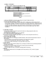
10. OPERATION:
A.
The receptacle can now be turned to the "ON" position by lifting the operating handle (11) to the upper-most position.
Please note that the receptacle can be turned "ON" with or without a mating plug engaged.
•
Safety feature
- The receptacle is interlocked to the operating handle mechanism so that a mating plug
may not be inserted or removed when the switch is in the "ON" position.
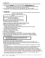
B. A hole is provided in the housing lock-out (12) and operating handle (11) for the use of a padlock
( See "FIGURE C") to prevent unauthorized movement of the operating handle (11) f
r
om the "OFF" position.
11. MAINTENANCE:
A. INSPECTION:
Receptacle must be inspected regularly. Schedule of inspections is determined by f
r
equency
of use and environmental conditions.
• It is recommended that inspections be carried out at least once a year.
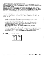
WARNING
If any parts of the "WSR" unit or the mating plug appear to be
missing, broken or show signs of damage:
DISCONTINUE USE IMMEDIATELY!
This condition could cause serious/fatal personal injury due to
electrocution and/or equipment damage. Repair with the proper
re lacement art s before continuin service.
DURING THE INSPECTIONS, PERFORM AT LEAST THE FOLLOWING:
1 . Electrical power must be turned "OFF" before performing maintenance.
2 . Inspect all conductor terminations for secureness.
• Retorque to values given previously in these instructions.
• Discoloration due to excessive heat is an indication of possible problems and should be thoroughly
investigated and repairs made as necessary.
3 . Check grounding and bonding effectiveness/continuity.
•
Retorque connections to original values.
4 .. Check gaskets for damage. Replace as necessary.
5 .. Clean interior of all foreign materials.
6. Cover bolts (2) must be tightened to 25 -30 lbs .. -ft. torque ..
7 . Make sure that receptacle assembly flip-cover (13) seals cover to receptacle housing face, if applicable.
8 . If applicable, make sure that receptacle assembly screw cover (21) seals cover to receptacle housing face.
9 .. Make sure the receptacle assembly nameplate located on the outside of the cover remains clean and legible.
•
Do not paint nameplate.
• It is recommended that an electrical preventive maintenance program,
such as found in the National Fire Protection Bulletin NFP A no. 70B,
be followed in addition to the above.
B. DISCONNECT SWITCH AND HANDLE ASSEMBLY:
Disconnect switches occasionally fail with use and need to be replaced .. The disconnect switch utilized in this
receptacle can be replaced with the same type and brand as factory installed. Doing so will not affect the U/L listing .
To remove disconnect switch from housing
-
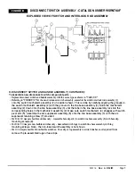
• Referring to "FIGURE C", remove the two handle lock-out screws (18) and remove housing lock-out (12) by lifting
it off of unit.
• Remove operating handle (11) from disconnect switch mechanism assembly (20) by carefully lifting off of assembly.
• Loosen the line side lug screws (7) of the disconnect switch and remove line side wi
r
es from the switch (15)..
• Loosen the load side lug screws (9) of the disconnect switch and remove wi
r
es from the switch (1.5). Please take
note of the orientation of these wires for proper reassembly. Also note that the wires (8) that connect the
receptacle to either the disconnect switch directly for the non-fused switches, or connect the receptacle
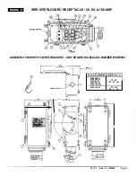
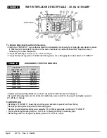
to the fuse block lugs (10) for the fuse switches are numbered according to phase location (See "FIGURE B")
• Remove disconnect switch and fuse base ( if applicable) mounting screws (17) . Remove disconnect switch (15)
and fuse base ( if applicable) (16) from housing (5).
Page 6
330118
Rev. A
3/28/95


