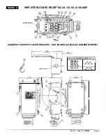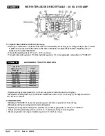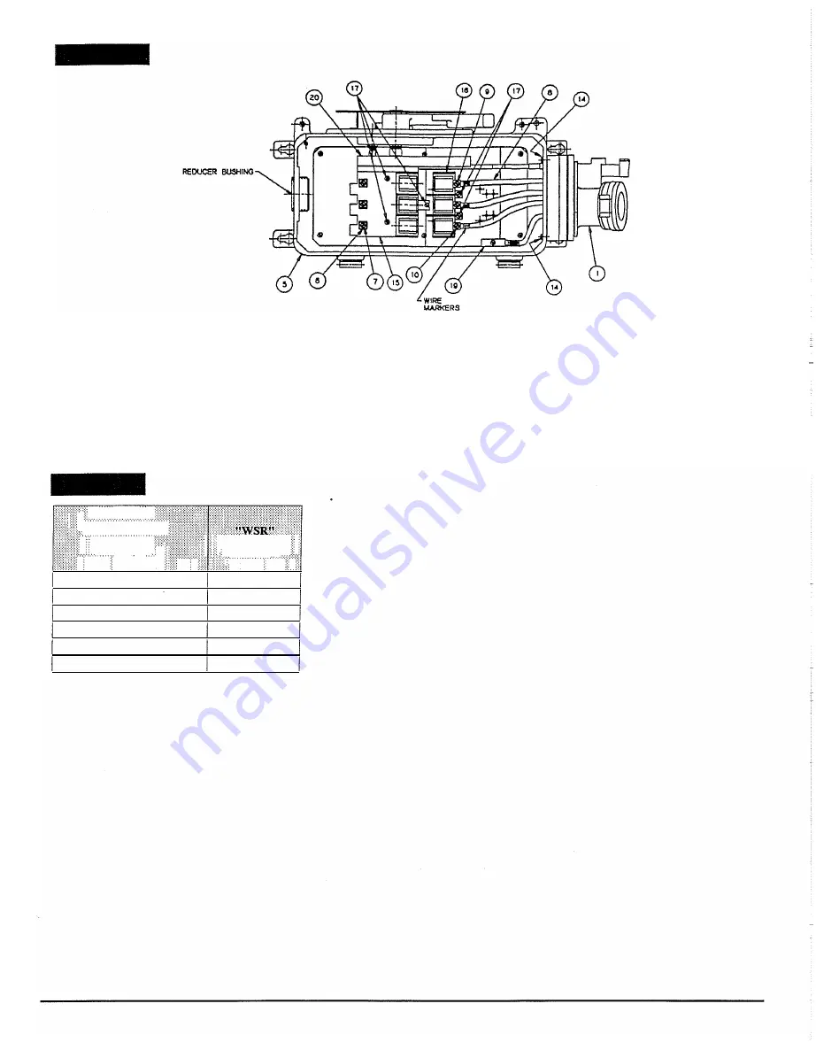
FIGURE C
WSR INTERLOCKED RECEPTACLE - 30, 60, & 100 AMP
To replace disconnect switch into housing -
• Refening to "FIGURE C", replace the disconnect switch assembly into housing by reversing the steps taken to remove
it.
Make sure to reconnect the wires to the same locations as before disassembly. Replace fuses, if
necessary, for fused receptacle.
• Torque the mounting screws (17) to 15 - 20 lb.-in. torque.
• Torque the line side lug screws (7) & the load side lug screws (9) to the appropriate values shown in "TABLE C".
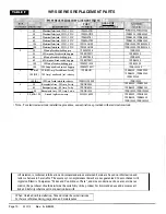
TABLE E
DISCONNECT SWITCH GROUPS
' iAPPLEToN' · ·
: ::•::nfscBW§iciH
r::::�wg;qn,}! : •• ; ••::;§�IM!&Xi I
Jij;\\¢.QRQV?�li
)JJ :
'='!1$:Ii'/PW.:t?
WSRNT30F
WSR3352
WSRNT30U
WSR33542
WSRNT60F
WSR6352
WSRNT60U
WSR63542
WSRNTlOOF
WSR10352
WSRNTlOOU
WSR103542
• Replace existing operating handle (11) with new one provided with disconnect switch group.
• Re-assemble housing lock-out (12) and the two handle lock-out screws (18) to housing (5) and tighten screws to
20 - 25 lb.-in. torque.
C. GROUND LUG
• Referring to "FIGURE C", loosen the ground lug screw and remove ground wi
r
e f
r
om the lug.
• Remove ground lug mounting screw from mounting plate ..
• Replace ground lug and mounting screw assembly (19) with the appropriate one shown in "TABLE F".
• Torque ground lug mounting screw to 16-20 lb..-in. to fasten ground lug to mounting plate.
• Reconnect ground wi
r
e to lug and tighten lug screw to 30-40 lb.-in. torque.
Page 8
330118
Rev. A 3/28/95


