29
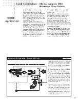
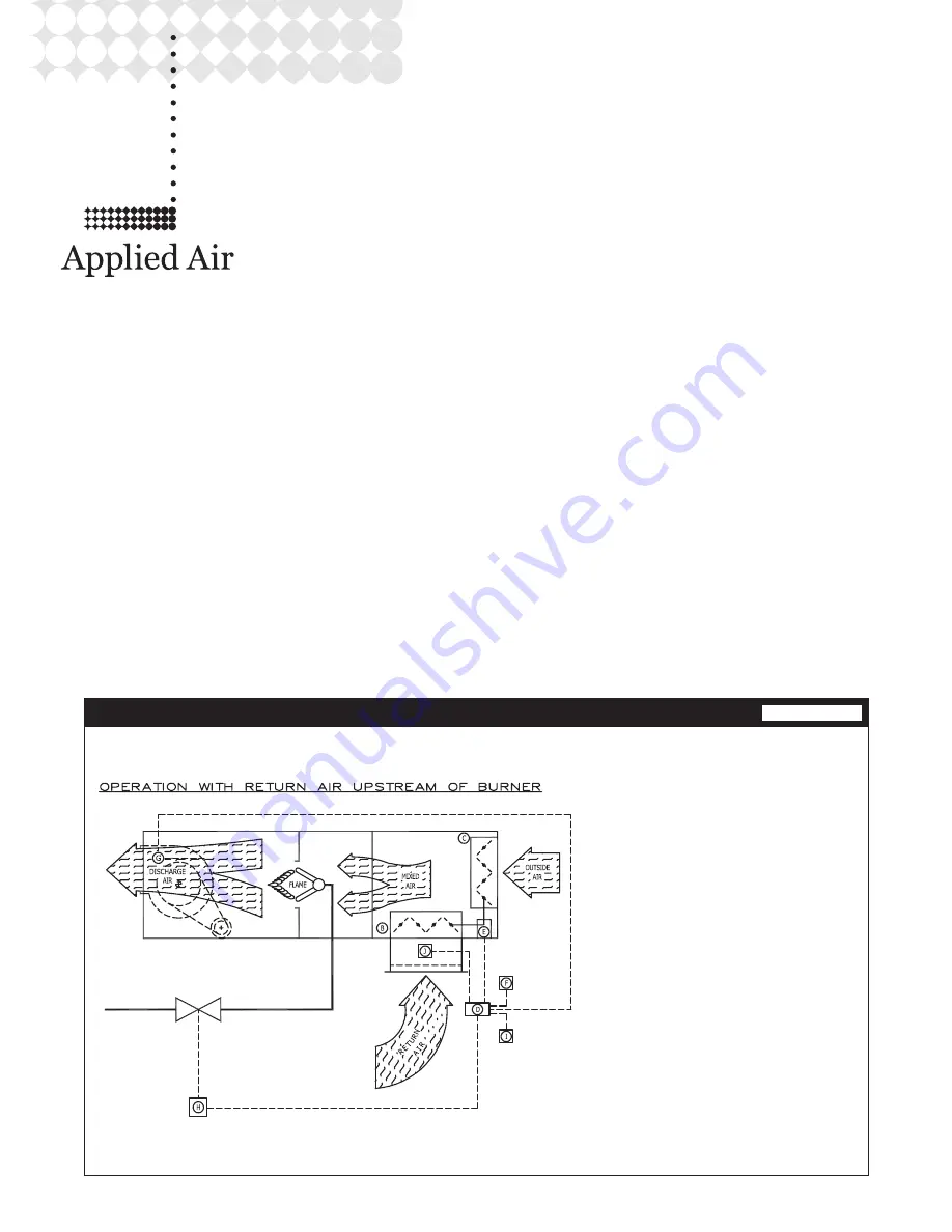
Sequence of Operation – Return Air Units
Signal from remote control I to AdaptAire
Controller D, sets operational parameters
for dampers B and C, and burner. Damper
operation can be manual, building pres-
sure or mixed air temperature.
Return air dampers B, and outside air
dampers C, are interlocked to move
together. As one opens, the other closes.
As the return air dampers open, allowing
more return air to enter the unit, the out-
side air dampers move toward the closed
position, decreasing the amount of outside
air. Pressure sensor and flow station J,
senses change in return airflow and signals
AdaptAire Controller D.
Modulating gas valve H, regulates gas
supply in response to signal from AdaptAire
Controller D. AdaptAire Controller D, var-
ies signal based on input from room tem-
perature sensor F, discharge temperature
sensor G, and airflow sensor J. Gas valve H
can provide approximately 4% to 100% of
rated burner capacity.
P000621
Guide Specification – Mixing Dampers With
Return Air Flow Station
Unit(s) shall have outside air and return
air dampers with modulating actuator
controlled by AdaptAire DDC control
system (Patent #7,059,536). The AdaptAire
DDC control system shall have capability
to digitally control the outside air quantity
from a nominal minimum of 20% to 100%
with integrated gas valve control at all room
concentrations of CO2.
The return air inlet shall include a self-
calibrating flow measuring station with a
grid of velocity pressure probes with spacing
no greater than 12” over the entire face of
the return air opening and sampled every
second. Samples are averaged to provide
smooth, accurate data that is delivered to
the AdaptAire DDC control system every
second. The DDC control system shall
be capable of electronically displaying
the return air/outside air ratio within 5%
accuracy at all damper positions.
The AdaptAire DDC control system shall be
capable of controlling mixing dampers in:
(Choose One)
Manual Mode:
The “Manual” mode allows
manual positioning of the outside air (O.A.)
damper and return air (R.A.) damper by
changing the damper position setpoint.
Mixed Air Temperature Mode:
The “Mixed
Air Temperature” mode shall provide auto-
matic control of the mixed air temperature by
modulating the outside air (O.A.) damper and
return air (R.A.) damper to maintain the mixed
air temperature setpoint.
Building Pressure Mode:
The “Building Pres-
sure” mode shall provide automatic building
pressure control by modulating the outside air
(O.A.) damper and return air (R.A.) damper to
maintain the indoor building pressure setpoint.
As the building pressure decreases below the
setpoint more outside air will be introduced.
Summary of Contents for DFL 035
Page 23: ...23 Gas Piping Layout Schematic Component Diagrams C000504 ...
Page 31: ...31 ...


