10
803809 Rev. 01
Room Freeze Protection
This feature is enabled when the unit is shipped from
the factory. The feature can be disabled by qualified
service personnel. If power is available to the unit, and
regardless of whether it is turned ON or OFF, the unit
will automatically supply heat to the room with the fan
running at low fan speed if the room temperature falls
to 50°F (10ºC). The heat will turn off when the room
temperature reaches 55°F (13ºC). For the feature to
work, the unit must be configured with an electric
heater. The feature is enabled whether the unit is
configured for keypad or remote thermostat. The
protection remains active when the unit is OFF, for
either keypad or remote thermostat application, as long
as the unit is plugged in, power is available, and a heat
source is configured in the unit and is working.
Compressor Short-Cycle Protection
If the electronic control shuts the compressor down for
any reason, a 3 minute time delay will elapse before the
compressor is allowed to re-start. This prevents
compressor overload during re-start due to unequal
system refrigerant pressures.
Indoor Coil Freeze Protection
Control of frost on the evaporator coil due to low
indoor loads, or cold outdoor ambient temperatures, is
provided.
Low Outdoor Temperature Lock-out
If the outdoor temperature is too low for proper
compressor operation, cooling operation will be
suspended until the outdoor temperature rises to an
acceptable point, depending on the application.
Indoor Temperature Limiting (Keypad Control
Only)
Using the keypad control and display, high and low
temperature limits can be established to prevent the
user from entering set point temperatures colder or
warmer than what the property manager or hotel
operator may desire. The temperature limit choices are
as follows:
Configuration Code
Low Limit °F
(ºC)
High Limit °F
(ºC)
R1
63 (17)
86 (30)
R2
65 (18)
86 (30)
R3
65 (18)
90 (32)
R4
67 (19)
88 (31)
R5
67 (19)
92 (33)
R6
69 (20)
90 (32)
R7
69 (20)
72 (22)
The procedure to set the limits is as follows:
Depress the On/Off key, the °F/°C key, and the
Warmer key simultaneously for 5 seconds to enter the
limit setup mode. The Warmer and Cooler keys will
scroll through the R-values indicated in the above
table. Once the desired R-value has been obtained on
the display, press the On/Off key to accept the change,
and then press it again to effect the change and restore
the normal display.
Automatic Powered Damper
NFWC models are available with or without provision
for fresh air. However, if the units are configured to
bring in fresh air, they must have an automatic powered
fresh air damper that opens the fresh air door to bring
outdoor air into the room only when the indoor blower
is running. If the indoor fan shuts off, the damper
automatically closes and interrupts the heating coil’s
potential exposure to possible extremely cold air when
there is no blended air flow over the coil and/or no
flow of the heating medium inside the coil. The factory
default is fresh air with high speed fan operation only,
but it can be changed to open with low speed fan
operation only by having qualified service personnel
re-wire the unit as shown on the specific wiring
diagram affixed to the unit.
WARNING:
The speed conversion procedure involves
exposure to high voltage electrical circuits in the
control box in order to make the necessary change to
the damper action tied to motor speed, and must be
performed by qualified service personnel. Failure to do
so could result in property damage, personal injury or
death. Disconnect electric power to the unit before
servicing.
OPTIONAL AIR DUCT KIT:
The NFWC series has been designed and certified
for use with an optional external duct kit. It is
recommended that only the Applied Comfort
Products duct kit be installed on the unit.
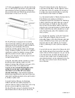
The NFWC has been designed to use a 4.5” tall by
7.5” wide insulated (3/8” insulation) Duct Plenum
fastened to the top of the unit, which connects to a
maximum 48” long insulated (1/4” insulation)
Extension Duct of the same size, and uses an Air
Terminal Grille at the end of the Extension Duct
having an actual outlet area of
7.25”x 4.25” with


