Installation and Service Manual – Metered Carbon Filter
Page 6
Copyright © 2012 Applied Membranes, Inc. All Rights Reserved.
Plumbing
Note:
All plumbing is to be done in accordance with state and local codes.
Caution:
Before placing wall anchors to support piping ensure that no electrical conduit or wiring is located
behind the intended mounting location.
Note:
The control valve, fittings and/or bypass are designed to accommodate minor plumbing misalignments
but are not designed to support the weight of a system or the plumbing.
Note:
Connect to a supply line downstream of outdoor spigots. Install an inlet shutoff valve and plumb them
to the unit’s inlet. Installation of a bypass valve is recommended. If using plastic fittings, ground the water
conditioner per local electrical codes. If a water meter is used, install the water meter on the outlet side of the
control valve. The turbine assembly may be oriented in any direction, but is usually oriented pointing up to reduce
drainage out of the pipe during service.
Note:
Do not use pipe dope or other sealant on threads. Use teflon tape on threaded inlet, outlet and drain
fittings.
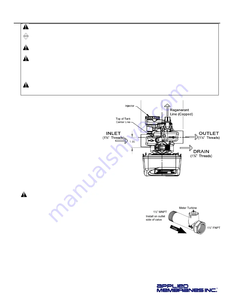
1. Install connecting piping between raw
water source and input pipe on control
valve.
2. Install drain line from control valve to
a free flowing drain.
A 1.25” Male NPT × 1.5” Female NPT SS
drain flow control is installed on the valve.
Solder joints near the drain must be done
prior to connecting the drain line flow
control fitting. Leave at least 6”
(152.4mm) between the drain line flow
control itting and the solder joints to
prevent heat from damaging the flow
control. Avoid elevating the drain line
above the control valve where possible.
Discharge the drain line through an air
gap to a receptacle in accordance with
local plumbing codes.
Important:
Never insert a drain line directly into a drain, sewer line or trap. Always allow an air gap between
the drain line and the receptacle to prevent back siphonage.
3. Install the water meter on the outlet side of the control valve
.
The meter may be threaded directly into the valve or may be
plumbed separately downstream of the unit*. Ensure the arrow on
the meter body is going the same direction as the water flow. The
turbine assembly may be oriented in any direction, but is usually
oriented pointing up to reduce drainage out of the pipe during
service. Meter can be installed horizontally or vertically.
*A longer cable (Part #V3221) is required for distances longer than 3” from
the valve body.


