background image

19

STF-R/C/D/IP Hardware Manual

920-0141 Rev. A

6/5/2018

conflicts or excessive traffic.  
1. 

If you use a desktop PC and have a spare card slot, install a second NIC and connect it directly to the drive using a 

CAT5 cable.  You don’t need a special “crossover cable”; the drive will automatically detect the direct connection and make 

the necessary physical layer changes.
2. 

If you use a laptop and only connect to your LAN using wireless networking, you can use the built-in RJ45 Ethernet 

connection as your second NIC.
3. 

Set the IP address on the drive to “10.10.10.10” by setting the rotary switch at “0”.

4. 

To set the IP address of the second NIC:

a. 

On Windows XP, right click on “My Network Places” and select properties.  

b. 

On Windows 7, click Computer.  Scroll down the left pane until you see “Network”.  Right click and select properties.  

Select “Change adapter settings”
5. 

You should see an icon for your newly instated NIC.  Right click again and select properties.  

a. 

Scroll down until you see “Internet Properties (TCP/IP)”.  Select this item and click the Properties button.  

b. 

On Windows 7 and Vista, look for “(TCP/IPv4)”

6. 

Select the option “Use the following IP address”.  Then enter the address “10.10.10.11”.  This will give your PC an IP 

address that is on the same subnet as the drive.  Windows will know to direct any traffic intended for the drive’s IP address to 

this interface card.
7. 

Next, enter the subnet mask as “255.255.255.0”.  Be sure to leave “Default gateway” blank.  This will prevent your PC 

from looking for a router on this subnet.
8. 

Because you are connected directly to the drive, anytime the drive is not powered on your PC will annoy you with a 

small message bubble in the corner of your screen saying “The network cable is unplugged.”

Summary of Contents for STF-C Series

Page 1: ...STF R C D IP Stepper Motor Drive Hardware Manual 920 0141 Rev A 6 5 2018 ...

Page 2: ...he Drive to Your PC using Ethernet D or IP model 16 2 6 Connecting the Power Supply 20 2 7 Choosing A Power Supply 21 2 8 Connecting the motor 22 3 Inputs and Outputs 23 3 1 Digital Inputs 24 3 2 Digital Outputs 26 4 Mounting the Drive 28 5 Reference Materials 29 5 1 Drive Mechanical Outlines 29 5 2 Technical Specifications 30 5 3 Numbering System 31 5 4 Ordering Information 31 5 6 Torque Speed cu...

Page 3: ...mmunication RS485 Modbus RTU CANopen Ethernet Modbus TCP Ethernet IP STF03 R STF06 R STF05 R STF10 R STF03 C STF06 C STF05 C STF10 C STF03 D STF06 D STF05 D STF10 D STF03 IP STF06 IP STF05 IP STF10 IP The Information in this manual applies to the following products ...

Page 4: ...d bus controlled stepper motor drive in compact package Operating DC voltage range STF03 12 48V STF05 24 48V STF06 12 48V STF10 24 70V Control Mode SCL Serial Communication Command Q program Stand Alone operation mode Modbus RTU R model only CANopen C model only Compliant with CiA301 and CiA402 standard Modbus TCP D and IP models EtherNet IP IP models Communication R Dual port RS 485 422 C Dual po...

Page 5: ...tical Isolation Input Optical Isolation Digital Filter Software Filter Digital Filter Software Filter Output Optical Isolation Single Ended Input Isolation X1 X1 X2 X2 X3 X3 X4 X4 X5 X6 X7 X8 XCOM Y1 Y2 Y3 YCOM Software Filter Motor RS 485 LED STF R Block Diagram Power Supply STF03 12 48VDC STF05 24 48VDC STF06 12 48VDC STF10 24 70VDC Y4 Y4 S2 RS 485 baud rate S1 RS 485 address 1 2 Block Diagram ...

Page 6: ...put Optical Isolation Input Optical Isolation Digital Filter Software Filter Digital Filter Software Filter Output Optical Isolation Single Ended Input Isolation X1 X1 X2 X2 X3 X3 X4 X4 X5 X6 X7 X8 XCOM Y1 Y2 Y3 YCOM Software Filter Motor ARM CANopen LED STF C Block Diagram Power Supply STF03 12 48VDC STF05 24 48VDC STF06 12 48VDC STF10 24 70VDC Y4 Y4 CANopen Baud rate CANopen Node ID S2 S1 ...

Page 7: ...High Speed Input Optical Isolation Input Optical Isolation Digital Filter Software Filter Digital Filter Software Filter Output Optical Isolation Single Ended Input Isolation X1 X1 X2 X2 X3 X3 X4 X4 X5 X6 X7 X8 XCOM Y1 Y2 Y3 YCOM Software Filter Motor Ethernet LED STF D IP Block Diagram Power Supply STF03 12 48VDC STF05 24 48VDC STF06 12 48VDC STF10 24 70VDC Y4 Y4 S1 IP address ...

Page 8: ...result in injury and damage to persons and machinery All technical information concerning the installation requirements must be strictly adhered to It is vital to ensure that all system components are connected to earth ground Electrical safety is impossible without a low resistance earth connection This product contains electrostatically sensitive components that can be damaged by incorrect handl...

Page 9: ...luded in the package It is used for connection with the next drive in the RS 485 network It can also be used for connection with PC for drive configuration C model A RS 232 programming cable included in the package A network cable is included in the package It is used for connection with the next drive in the CANopen network D IP models A Ethernet network cable is included in the package It is use...

Page 10: ...network cable included in the package Connect the C model drive to the RS 232 port of the PC using the RS 232 cable included in the package Connect the D IP model Drive to the Ethernet port of the PC The connectors and other points of interest are illustrated below STF05 10 STF03 06 Ground Screws LED RS 485 or CANopen Communication Connector Motor Connector Power Connector I O Connector Band Rate ...

Page 11: ...nnection or 2 wire connection can be used RS 485 four wire connection RS 485 two wire connection Drive Connection RX Connect to host s TX RX Connect to host s TX TX Connect to host s RX TX Connect to host s RX GND Connect to host s GND Drive Connection RX Connect to host s RX Connect to host s TX Connect to host s TX Connect to host s GND Connect to host s GND NOTE The RS 485 port on the drive is ...

Page 12: ...e drive s TX to the RX terminal of the host controller and connect the drive s TX to the RX terminal of the host controller Connect the drive s GND and the host s GND to a same ground RS 485 Two wire Configuration In a two wire system the data transmitting and receiving use a same cable the host must stop its transmitting before receiving data That means the host must stop transmit data before dri...

Page 13: ...cable Before using STF configurator for C drive configuration please connect COM1 on the driver to host PC by RS 232 programming cable CANopen network connection Multiple C model drive network can be built via dual CANopen communication port by network cable provided NOTE The CANopen port on the drive is isolated from internal circuitry of the drive So the GND of each drive s CANopen port must be ...

Page 14: ...witch S2 S1 is used to set drive s RS 485 address and the range is 0 F 0 15 in decimal If you want to set the drive s RS 485 address range to 10 1F 16 31 in decimal you need to configure it in STF Configurator software Upper Lower addr S1 position SCL addr Upper Lower addr S1 position SCL addr Lower Axis 0 15 0 0 Upper Axis 16 31 0 1 1 1 2 2 2 3 3 3 4 4 4 5 5 5 6 6 6 7 7 7 8 8 8 9 9 9 A A B B C C ...

Page 15: ...ed using rotary switches and software one sixteen position switch set the lower four bits 0 F of node ID while upper three bits of node ID are configured by STF Configurator software Each time when Node ID is changed a power cycle is required before the new Node ID is valid Please refer to the CANopen manual for more information CANopen Baud Rate There are 8 types of baud rate supported by CANopen...

Page 16: ...bnet mask then your machine can only talk to another network device whose IP address matches yours in the first three octets The numbers between the dots in an IP address are called octets For example if your PC is on a Class C subnet and has an IP address of 192 168 0 20 it can talk to a device at 192 168 0 40 but not one at 192 168 1 40 If you change your subnet mask to 255 255 0 0 Class B you c...

Page 17: ...r PC If you are on a corporate network please check with your system administrator before connecting anything new to the network He or she should be able assign you a suitable address and help you get going If you are not sure which addresses are already used on your network you can find out using Angry IP scanner which can be downloaded free from http www angryip org w Download But be careful an ...

Page 18: ...to Your PC It doesn t get much simpler than this 1 Connect one end of a CAT5 Ethernet cable into the LAN card NIC on your PC and the other into the drive You don t need a special crossover cable the drive will automatically detect the direct connection and make the necessary physical layer changes 2 Set the IP address on the drive to 10 10 10 10 by setting the rotary switch at 0 3 To set the IP ad...

Page 19: ...left pane until you see Network Right click and select properties Select Change adapter settings 5 You should see an icon for your newly instated NIC Right click again and select properties a Scroll down until you see Internet Properties TCP IP Select this item and click the Properties button b On Windows 7 and Vista look for TCP IPv4 6 Select the option Use the following IP address Then enter the...

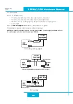
Page 20: ...ge from 12 48VDC STF05 accepts DC voltage range from 24 48VDC STF06 accepts DC voltage range from 12 48VDC STF10 accepts DC voltage range from 24 70VDC Warning DO NOT reverse the wires NOTE DO NOT apply power until all connections to the drive have been made V J1 V Power Connector Ensure a proper earth ground connection by using the screw on the left side of the chassis To Earth Ground Please read...

Page 21: ...as 75VDC maximum for STF10 and 53VDC maximum for STF05 When operation below 18VDC the STF05 10 series will work unstable The supply input cannot go blow 18VDC for reliable operation otherwise under voltage alarm will be triggered STF05 10 drive will stop working when this alarm is triggered For STF10 drives If a regulated power supply is used and that is near the driver maximum voltage of 75VDC a ...

Page 22: ... see below A A B B 4 lead motor Red Blue Yellow White 4 Leads Eight lead motors can also be connected in two ways series and parallel As with six lead motors series operation gives you less torque at high speeds but may result in lower motor losses and less heating In series operation the motor should be operated at 30 less than the unipolar rated current The motors recommended in this manual shou...

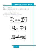
Page 23: ...s include 8 optically isolated digital inputs 5 24VDC for high level voltage 4 optically isolated digital outputs maximum voltage 30V maximum sinking or sourcing current 100mA 2 4 6 8 10 12 14 16 18 20 1 3 5 7 9 11 13 15 17 19 X1 X2 X3 X4 X5 X7 Y1 Y3 Y4 XCOM YCOM X1 X2 X3 X4 X6 X8 Y2 Y4 J2 I O Connector Diagram ...

Page 24: ...be used as CW limit input or general purpose input X4 can be used as CCW limit input or general purpose input Please use STF Configurator software for X1 X2 X3 and X4 function configuration Following graphs shows some common connection methods for the inputs STF Drive Switch or Relay closed logic Low X1 2 3 4 X1 2 3 4 5 24 VDC Power Supply STF Drive NPN Output X1 2 3 4 X1 2 3 4 output 5 24 VDC Powe...

Page 25: ...to the input you must need a power supply XCOM is an electronics term for a single ended signal connection to a common voltage In the case of STF series if you are using a sourcing PNP input signals you need to connect XCOM to the ground power supply if you are using a sinking NPN input signals the XCOM need to connect to the power supply Please use STF Configurator software for X5 X6 X7 and X8 fu...

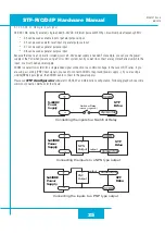
Page 26: ...ply And the current of each output terminal must not exceed 100mA Connecting a sinking output Connecting a sinking output with PLC s input Connecting a sourcing output with PLC s input STF Drive 5 24 VDC Power Supply Load YCOM Y1 2 3 C L P C D V 4 2 5 y l p p u S r e w o P YCOM Y1 2 3 IN COM STF Drive PLC 5 24VDC Power Supply YCOM Y1 2 3 COM IN STF Drive STF 5 24 VDC Power Supply relay Y1 2 3 Conn...

Page 27: ...or the outputs NOTE Do not connect the outputs to more than 30VDC power supply And the current of each output terminal must not exceed 100mA Y4 Y4 Y4 Y4 Y4 Y4 Y4 Y4 C L P IN COM PLC COM IN relay STF Drive STF Drive STF Drive STF Drive Connecting a sinking output Connecting a sinking output with PLC s input Connecting a sourcing output with PLC s input Load 5 24VDC Power Supply 5 24VDC Power Supply...

Page 28: ...at metal surface the will help conduct heat away from the chassis If this is not possible forced airflow from a fan maybe required to prevent the drive from overheating Never use the drive in a place where there is no air flow or the surrounding air is more than 40 C Never put the drive where it can get wet or where metal or other electrically conductive particle particles can get on the circuity ...

Page 29: ...rdware Manual 920 0141 Rev A 6 5 2018 5 Reference Materials 5 1 Drive Mechanical Outlines STF03 06 4 5 3 5 49 8 61 8 86 6 23 5 16 7 8 157 6 100 93 93 Unit mm STF05 10 142 5 11 6 29 17 78 2 50 4 5 4 5 122 122 129 Unit mm ...

Page 30: ...y and allow stable operation throughout the speed range of the motor Torque Ripple Smoothing Allows for fine adjustment of phase current waveform harmonic content to reduce low speed torque ripple in the range of 0 25 to 1 5 rps Auto Test Auto Setup Auto test and setup at power on ie motor resistance and capacitance to optimize your system performance Non Volatile Storage Configurations are saved ...

Page 31: ... 6A peak of sine 10 10A peak of sine Communication Control R RS 485 with Q programming Modbus RTU C CANopen D Dual port Ethernet with Q programming Modbus TCP IP Dual port Ethernet IP with Q programming Modbus TCP Series STF Stepper Series 5 4 Ordering Information Model Voltage RS 485 Modbus RTU CANopen Ethernet Modbus TCP Ethernet IP STF03 R 12 48 VDC STF05 R 24 48 VDC STF06 R 12 48 VDC STF10 R 2...

Page 32: ...01 601 264 19 0 5 0 0 5 1 6 480 HT23 603 354 25 48 6 0 0 5 2 2 750 HT24 100 123 2 8 87 3 36 0 73 1 6 260 HT24 105 177 12 74 4 8 0 43 1 1 450 HT24 108 354 25 48 4 8 0 65 2 4 900 HT34 486 1200 86 4 9 7 0 27 2 2 2680 HT34 487 1845 133 10 0 0 27 2 4 4000 HT34 504 396 5 28 55 7 56 0 24 1 7 1100 HT34 505 849 6 61 18 7 56 0 33 2 7 1850 HT34 506 1260 90 75 6 72 0 63 5 4 2750 Note The Drive Current Setting...

Page 33: ...15 20 25 0 5 10 15 20 25 30 35 40 oz in rev sec 5014 042 842 1 2 A phase HT11 013 213 1 2 A phase HT11 012 212 1 2 A phase HT17 24 VDC power supply 20000 steps rev all motors connected in parallel 0 10 20 30 40 50 60 70 80 90 100 0 5 10 15 20 25 30 35 40 oz in rev sec HT17 278 2 4 A phase HT17 075 275 2 0 A phase HT17 071 271 2 0 A phase HT17 068 268 1 6 A phase ...

Page 34: ...10 15 20 25 30 35 40 oz in rev sec HT17 278 2 4 A phase HT17 075 275 2 0 A phase HT17 071 271 2 0 A phase HT17 068 268 1 6 A phase HT23 24 VDC power supply 20000 steps rev all motors connected in parallel 0 50 100 150 200 250 300 350 0 5 10 15 20 25 30 35 40 oz in rev sec HT23 603 6 0 A phase HT23 401 601 5 0 A phase HT23 398 598 5 0 A phase HT23 394 594 3 4 A phase ...

Page 35: ...50 100 150 200 250 300 350 0 5 10 15 20 25 30 35 40 oz in rev sec HT23 603 6 0 A phase HT23 401 601 5 0 A phase HT23 398 598 5 0 A phase HT23 394 594 3 4 A phase HT24 24 VDC power supply 20000 steps rev 0 50 100 150 200 250 300 350 0 5 10 15 20 25 30 35 40 oz in rev sec HT24 108 4 8 A phase HT24 105 4 8 A phase HT24 100 3 36 A phase ...

Page 36: ...50 0 5 10 15 20 25 30 35 40 oz in rev sec HT24 108 4 8 A phase HT24 105 4 8 A phase HT24 100 3 36 A phase HT34 485 486 487 24 VDC power supply 20000 steps rev all motors connected in parallel 0 200 400 600 800 1000 1200 1400 0 5 10 15 20 25 30 35 40 oz in rev sec HT34 487 10 A phase HT34 486 9 7 A phase HT34 485 10 A phase ...

Page 37: ...0 400 600 800 1000 1200 1400 0 5 10 15 20 25 30 35 40 oz in rev sec HT34 487 10 A phase HT34 486 9 7 A phase HT34 485 10 A phase HT34 485 486 487 80 VDC power supply 20000 steps rev all motors connected in parallel 0 200 400 600 800 1000 1200 1400 0 5 10 15 20 25 30 35 40 oz in rev sec HT34 487 10 A phase HT34 486 9 7 A phase HT34 485 10 A phase ...

Page 38: ...00 600 700 800 900 1000 0 5 10 15 20 25 30 35 40 oz in rev sec HT34 506 6 72 A phase HT34 505 7 56 A phase HT34 504 7 56 A phase HT34 504 505 506 48 VDC power supply 20000 steps rev all motors connected in parallel 0 100 200 300 400 500 600 700 800 900 1000 0 5 10 15 20 25 30 35 40 oz in rev sec HT34 506 6 72 A phase HT34 505 7 56 A phase HT34 504 7 56 A phase ...

Page 39: ... A 6 5 2018 HT34 504 505 506 60 VDC power supply 20000 steps rev all motors connected in parallel 0 100 200 300 400 500 600 700 800 900 1000 0 5 10 15 20 25 30 35 40 oz in rev sec HT34 506 6 72 A phase HT34 505 7 56 A phase HT34 504 7 56 A phase ...

Page 40: ...pically reaches maximum temperature after 30 to 45 minutes of operation If you run the motor for one minute then let it sit idle for one minute that is a 50 duty cycle Five minutes on and five minutes off is also 50 duty However one hour on and one hour off has the effect of 100 duty because during the first hour the motor will reach full and possibly excessive temperature The actual temperature o...

Page 41: ...le vs Speed 48 VDC 1 60 Amps 40 C Ambient on 4 75 x 4 75 x 25 Aluminum Plate 0 20 40 60 80 100 0 10 20 30 40 50 Speed RPS Duty Cycle HT17 071 Max Duty Cycle vs Speed 24 VDC 2 0 Amps 40 C Ambient on 4 75 x 4 75 x 25 Aluminum Plate 0 20 40 60 80 100 0 10 20 30 40 50 Speed RPS Duty Cycle HT17 071 Max Duty cycle vs Speed 48 VDC 2 0 Amps 40 C Ambient on 4 75 x 4 75 x 25 Aluminum Plate 0 20 40 60 80 100...

Page 42: ...ty Cycle vs Speed 48 VDC 3 4 Amps 40 C Ambient on 6 4 x 6 4 x 25 Aluminum Plate 0 20 40 60 80 100 0 10 20 30 40 50 Speed RPS Duty Cycle HT23 398 Max Duty cycle vs Speed 24VDC 5 0A 40 C Ambient on 6 4 x 6 4 x 25 Aluminum Plate 0 20 40 60 80 100 0 10 20 30 40 50 Speed RPS Duty Cycle HT23 398 Max Duty cycle vs Speed 0 20 40 60 80 100 0 10 20 30 40 50 Speed RPS Duty Cycle 48VDC 5 0A 40 C Ambient on 6 ...

Page 43: ...cle vs Speed 48 VDC 10 0 Amps 40 C Ambient on 10 x 10 x 5 Aluminum Plate 0 20 40 60 80 100 0 10 20 30 40 50 Speed RPS Duty Cycle HT34 486 Max Duty cycle vs Speed 80 VDC 10 0 Amps 40 C Ambient on 10 x 10 x 5 Aluminum Plate 0 20 40 60 80 100 0 10 20 30 40 50 Speed RPS Duty Cycle HT34 487 Max Duty Cycle vs Speed 48 VDC 10 0 Amps 40 C Ambient on 10 x 10 x 5 Aluminum Plate 0 20 40 60 80 100 0 10 20 30 ...

Page 44: ...led 2 red 1 green CCW limit 2 red 2 green CW limit 3 red 1 green drive over temperature 3 red 2 green internal voltage bad 3 red 3 green blank Q segment 4 red 1 green over voltage 4 red 2 green under voltage 5 red 1 green over current 6 red 1 green open motor winding 7 red 1 green communication error NOTE Items in bold italic represent Drive Faults which automatically disable the motor ...

Page 45: ...using 501646 2000 Molex Crimp 501648 1000 Molex L 19 20 2 J1 1 50 5 P N Length 3004 348 2m Pin No Assignment Description Color Pin No Assignment Description Color 1 X1 X1 Digital Input Blue White 11 X7 X7 Digital Input Yellow 2 X1 Blue Black 12 X8 X8 Digital Input Green 3 X2 X2 Digital Input Green White 13 SHIELD Shield Shield 4 X2 Green Black 14 XCOM X5 X8 Digital Input COM Red 5 X3 X3 Digital In...

Page 46: ...wer supply This can trip the overvoltage protection of a switching power supply causing it to shut down Applied Motion Products offers the RC880 regeneration clamp to solve this problem If in doubt use an RC880 for the first installa tion If the regen LED on the RC880 never flashes you don t need the clamp USB Serial Adapter P N 8500 003 76 45 94 85 85 28 6 Power Supplies P N Power Voltage PS150A2...

Page 47: ...47 STF R C D IP Hardware Manual 920 0141 Rev A 6 5 2018 ...

Page 48: ...48 STF R C D IP Hardware Manual 920 0141 Rev A 6 5 2018 7 Contacting Applied Motion Products 404 Westridge Dr Watsonville CA 95076 USA 1 800 525 1609 www applied motion com ...

Reviews: