22
STF-R/C/D/IP Hardware Manual
920-0141 Rev. A
6/5/2018
2.8 Connecting the motor
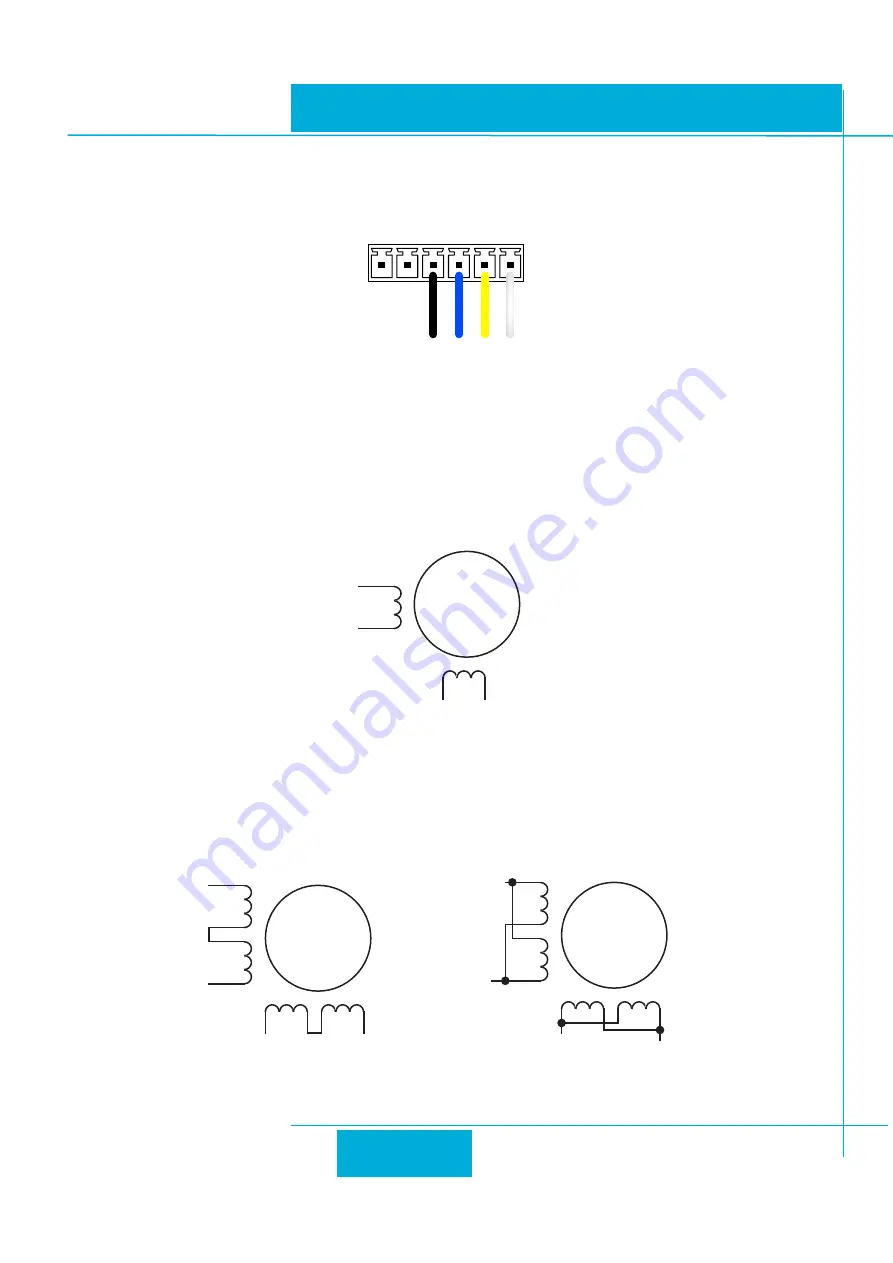
For Applied Motion Products’stepper motor, please connect black, green, red, blue wires to drive’s A+, A-, B+ and B-
correspondingly.
A+
J1
A- B+ B-
Motor Connector
Never connect or disconnect the motor while the power is on.
If using a non-Applied Motion Products motor, please refer to your motor specs for wiring information. Do not connect it until
you have configured the drive for that motor.
Four lead motors can only be connected one way. see below
A+
A–
B+
B–
4
lead
motor
Red
Blue
Yellow
White
4 Leads
Eight lead motors can also be connected in two ways: series and parallel. As with six lead motors, series operation gives
you less torque at high speeds, but may result in lower motor losses and less heating. In series operation, the motor should
be operated at 30% less than the unipolar rated current. The motors recommended in this manual should be connected in
parallel. The wiring diagrams for eight lead motors are shown on the following page.
A+
A–
B+
B–
8
lead
motor
8 Leads Series Connected
8 Leads Parallel Connected
A+
A–
B+
B–
8
lead
motor
Orange
Org/Wht
Blk/Wht
Black
Red Red/
Wht
Yel/
Wht
Yellow
Orange
Org/
Wht
Blk/Wht
Black
Red
Red/Wht
Yel/
Wht
Yel
low


