background image

16

920-0082

Rev. B

TSM23C Hardware Manual

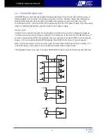
3.3.2  X1 & X2 Digital Input

The TSM23C drives include two inputs: X1 and X2. They accept 5 to 24 volt single-ended or 

differential signals. The diagrams below show how to connect them to various commonly used 

devices.

+5v to +24v out

X1

X2

X1+

X1-

X2+

X2-

Indexer 

with 

Sinking

Outputs

Connecting to Indexer with Sinking Outputs

TSM23C

X2

COM

X1

Indexer

with

Sourcing

Outputs

X2+

X2-

X1+

X1-

Connecting to Indexer with Sourcing Outputs

TSM23C

X2+

X2-

X1+

X1-

5 - 24

volt DC

Power

Supply

Using Mechanical Switches

+

TSM23C

Summary of Contents for TSM23C

Page 1: ...TSM23C Integrated Step Servo Motor Hardware Manual 920 0082 Rev B ...

Page 2: ...munications 13 3 2 1 Node ID 14 3 2 2 Setting the Bitrate 14 3 3 Inputs and Outputs 15 3 3 1 Connector Pin Diagram 15 3 3 2 X1 X2 Digital Input 16 3 3 3 X3 X4 X5 X6 Digital Input 17 3 3 4 X7 X8 Digital Input 18 3 3 5 Programmable Output Y1 Y2 Y3 19 3 3 6 Programmable Output Y4 20 4 Troubleshooting 21 4 1 LED Error Codes 21 5 Reference Materials 22 5 1 Torque Speed Curves 22 5 2 Mechanical Outlines...

Page 3: ... 402 Profile Torque Profile Velocity Profile Position Homing Q Programing Execute stored Q programs via Applied Motion Products specific CANopen objects Communications CANopen RS 232 5000 line 20 000 counts rev encoder feedback Available torque TSM23C 2CG Up to 1 0 N m Continuous 1 3 N m Boost TSM23C 3CG Up to 1 5 N m Continuous 2 0 N m Boost TSM23C 4CG Up to 2 4 N m Continuous 3 2 N m Boost I O 8...

Page 4: ...Over Current Detect motor encoder 5 Volt DC Power Supply DSP Driver Controller 3 3VDC Internal Logic Supply TSM23C I O Connector 5VDC 100mA max GND Status AIN Optical Iso RS 232 CANopen Comm Conn Power Conn GND 5V RS 232 RXD 5V TXD GND GND and CANopen CANH CANL GND X1 X2 X3 X4 X5 X6 X7 X8 Y1 Y2 Y3 Y4 Optical ISO A A B B Z Z Line Driver Encoder Outputs ...

Page 5: ...n injury and damage to persons and machinery All technical information concerning the installation requirements must be strictly adhered to It is vital to ensure that all system components are connected to earth ground Electrical safety is impossible without a low resistance earth connection This product contains electrostatically sensitive components that can be damaged by incorrect handling Foll...

Page 6: ...all the Step Servo Quick Tuner software from the Applied Motion Products website Connect the drive to the PC using the programming cable Connect the drive to the power supply See instructions below Launch the software by clicking Start Programs Applied Motion Products Apply power to the drive The software will recognize the drive and display the model and firmware version At this point it is ready...

Page 7: ...solute minimum power supply input is 10 VDC If the Input supply drops below 10 VDC the low voltage alarm will be triggered This will not fault the drive Absolute maximum power supply input is 75 VDC at which point an over voltage alarm and fault will occur When using a power supply that is regulated and is near the drive maximum voltage of 75 VDC a voltage clamp may be required to prevent over vol...

Page 8: ... less current will be required from the power supply It is important to note that the current draw is significantly different at higher speeds depending on the torque load to the motor Estimating how much current is necessary may require a good analysis of the load the motor will encounter 0 0 5 1 1 5 2 2 5 3 3 5 0 0 3 0 6 0 9 1 2 1 5 0 10 20 30 40 50 Torque N m Speed RPS TSM23C 2CG 24V Power Amps...

Page 9: ...ue Boost Supply Current Full Load No Load 0 0 5 1 1 5 2 2 5 3 3 5 0 0 5 1 1 5 2 2 5 0 10 20 30 40 50 Torque N m Speed RPS TSM23C 3CG 24V Power Amps Continuous Torque Boost Supply Current Full Load No Load 0 0 5 1 1 5 2 2 5 3 3 5 0 0 5 1 1 5 2 2 5 0 10 20 30 40 50 Torque N m Speed RPS TSM23C 3CG 48V Power Amps Continuous Torque Boost Supply Current Full Load No Load ...

Page 10: ... Boost Supply Current Full Load No Load 0 0 5 1 1 5 2 2 5 3 3 5 4 4 5 0 1 2 3 4 5 0 10 20 30 40 50 Torque N m Speed RPS TSM23 4 G 48V Power Amps Continuous Torque Boost Supply Current Full Load No Load 0 0 5 1 1 5 2 2 5 3 3 5 0 0 5 1 1 5 2 2 5 0 10 20 30 40 50 Torque N m Speed RPS TSM23C 3CG 70V Power Amps Continuous Torque Boost Supply Current Full Load No Load ...

Page 11: ...11 920 0082 Rev B TSM23C Hardware Manual 0 0 5 1 1 5 2 2 5 3 3 5 4 4 5 0 1 2 3 4 5 0 10 20 30 40 50 Torque N m Speed RPS TSM23 4 G 70V Power Amps Continuous Torque Boost Supply Current Full Load No Load ...

Page 12: ...install a 6 3 amp fast acting fuse in line with the power supply lead Be careful not to reverse the wires Reversing the connection may open the internal fuse on the drive and void the warranty The RC880 regeneration clamp is for use where regeneration from the motor may cause damage to the drive In these cases the RC880 is connected between the drive and power supply and absorbs regenerated energy...

Page 13: ... the serial port of the PC Plug the 5 pin crimp style connector into one of the two appropriate connector on the TSM23C Secure the cable to the PC with the screws on the DB9 connector Note If the PC does not have an RS 232 serial port a USB Serial Converter will be needed You can contact Applied Motion Products to buy a USB to RS 232 converter The RS 232 circuitry does not have any extra electrica...

Page 14: ...e seven bits long with a range of 1 127 or 0x01 0x7F in hexadecimal notation Node ID 0x00 is reserved in accordance with the CiA 301 specification 3 2 2 Setting the Bitrate The CANopen network bitrate is set by the ten position switch in the front of the drive The bit rate must be the same for all nodes on the CANopen network Any changes to the bit rate require either a power cycle or a CANopen re...

Page 15: ...ingle ended inputs and can be used for Motor Enable Disable and Alarm Fault Reset function input X5 X6 are digital inputs for single ended signal They are general purpose inputs X7 X8 are digital inputs for differential or single ended signal They can be configured by software to be CW CCW Limit input signal 3 3 1 Connector Pin Diagram A B Z Y4 YCOM Y2 X8 X7 GND 5V X6 X4 X2 X1 A B Z Y4 Y3 Y1 X8 X7...

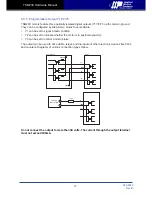
Page 16: ...signals The diagrams below show how to connect them to various commonly used devices 5v to 24v out X1 X2 X1 X1 X2 X2 Indexer with Sinking Outputs Connecting to Indexer with Sinking Outputs TSM23C X2 COM X1 Indexer with Sourcing Outputs X2 X2 X1 X1 Connecting to Indexer with Sourcing Outputs TSM23C X2 X2 X1 X1 5 24 volt DC Power Supply Using Mechanical Switches TSM23C ...

Page 17: ...ctronics term for an electrical connection to a common voltage Sometimes common means the same thing as ground but not always In the case of the TSM23 drives if you are using sourcing PNP input signals then you will want to connect COM to ground power supply If you are using sinking NPN signals then COM must connect to power supply Note If current is flowing into or out of an input the logic state...

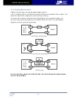
Page 18: ...how how to connect the X7 X8 Inputs to various commonly used devices 5 24 volt DC Power Supply Connecting an NPN type Proximity Sensor to an Input when prox sensor activates input goes low X7 X8 X7 X8 NPN Proximity Sensor output TSM23C 5 24 volt DC Power Supply Connecting a PNP type Proximity Sensor to an Input when prox sensor activates input goes high X7 X8 X7 X8 PNP Proximity Sensor output TSM2...

Page 19: ...ition Y2 can be set to indicate whether the motor is in position dynamic Y3 can be set to control a motor brake The output can be used to drive LEDs relays and the inputs of other electronic devices like PLCs and counters Diagrams of various connection types follow Do not connect the output to more than 30 volts The current through the output terminal must not exceed 100mA 5 24VDC 0VDC Y1 YCOM Y2 ...

Page 20: ...frequency proportional to motor speed tach signal or to provide a timing outout 50 pulses rev or to indicate whether the motor is in position static Diagrams of various connection types follow Do not connect the output to more than 30 volts The current through the output terminal must not exceed 100mA Y4 Y4 5 24 volt DC Power Supply Connecting a Sinking Output Load TSM23C COM IN Y4 Y4 PLC Connecti...

Page 21: ...hich warnings may be masked Code Error Solid green no alarm motor disabled Flashing green no alarm motor enabled 1 red 1 green motor stall optional encoder only 2 red 1 green ccw limit 2 red 2 green cw limit 3 red 1 green drive overheating 3 red 2 green internal voltage out of range 3 red 3 green blank Q segment 4 red 1 green power supply overvoltage or excess regen 4 red 2 green power supply unde...

Page 22: ...continuous 7 5 amp rating is boost 0 0 5 1 1 5 2 2 5 3 3 5 0 10 20 30 40 50 Torque N m Speed rps TSM23 4 G 24V 48V 70V 24V 48V 70V Continuous Boost 0 0 3 0 6 0 9 1 2 1 5 0 10 20 30 40 50 Torque N m Speed rps Continuous Boost 24V 48V 70V 24V 48V 70V TSM23C 2CG Continuous Boost 24V 48V 70V 24V 48V 70V 0 0 5 1 1 5 2 2 5 0 10 20 30 40 50 Torque N m Speed rps TSM23C 3CG ...

Page 23: ...0082 Rev B TSM23C Hardware Manual 5 2 Mechanical Outlines Unit mm Model Length L TSM23C 2CG 95 6 TSM23C 3CG 117 6 TSM23C 4CG 120 6 47 14 47 14 Ø38 1 4 Ø5 1 1 6 7 L 56 2 Ø8 7 5FLAT 24 20 70 6 76 7 56 2 50 9 75 ...

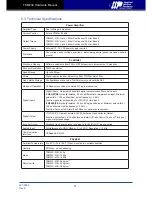
Page 24: ...puts Digital Inputs Adjustable bandwidth digital noise rejection filter on all inputs X1 X2 X7 X8 Optically isolated 5 24 volt differential or single ended input Minimum pulse width 100 μs Maximum pulse frequency 5 KHz Function general purpose input or CW CCW Limit input X3 X4X5 X6 Optically isolated 5 24 volt single ended input Minimum pulse width 100 μs Maximum pulse frequeny 5 KHz Function Serv...

Page 25: ...ed by regeneration is transferred back to the power supply This can trip the overvoltage protection of a switching power supply causing it to shut down Applied Motion Products offers the RC880 regeneration clamp to solve this problem If in doubt use an RC880 for the first installation If the regen LED on the RC880 never flashes you don t need the clamp USB Serial Adapter P N 8500 003 USB to RS 232...

Page 26: ...26 920 0082 Rev B TSM23C Hardware Manual 5 5 Cables I O P N 3004 318 2M Included RS 485 and CANOpen P N 3004 313 1M Included ...

Page 27: ...n Model Supplier Description Model Supplier Power RS232 Connector 1615780000 Weidmuller Housing ZER 04V S JST I O Pin Connector SZE 002T P0 3 JST Housing PUDP 28V S JST RS 485 CANOpen Pin Connector SPUD 001T P0 5 JST Housing ZER 05V S JST Pin Connector SZE 002T P0 3 JST ...

Page 28: ...28 920 0082 Rev B TSM23C Hardware Manual 6 Contacting Applied Motion Products 404 Westridge Dr Watsonville CA 95076 USA 1 800 525 1609 www applied motion com ...

Reviews: