4
Termination switch
When engaged the termination switch places a 120ohm resistor between
pin number 2 & 3 of the 5 pin input XLR connector. This resistor prevents data
reflection back down the transmission line. The terminator should only be
engaged when no other devices are connected to the loop-out data connector.
If other devices are connected to the loop-out connector the last device should
be appropriately terminated.
When lit the 3 LED indicators on the front of the Omni Splitter inform the user that:
✔
POWER – The universal power supply is converting input voltage to 5VDC
✔
SIGNAL – Digital data is being passed by the RS-485 receiving chip
✔
TERM – The termination switch is pushed in and the line is terminated
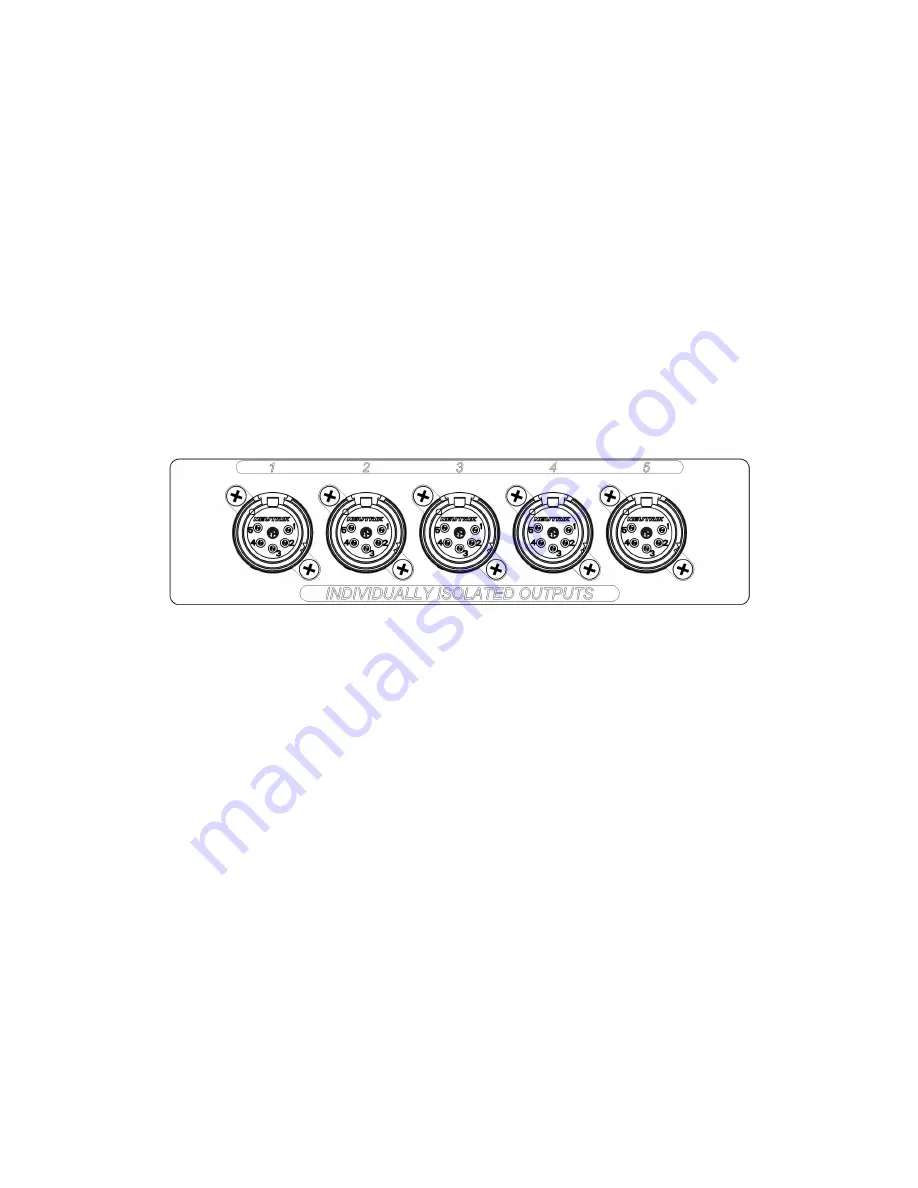
Data output
•
XLR output data connectors are provided for feeding DMX to up to 32
receivers each.
•
The power supply for each output is galvanically isolated from the input and
the other outputs.
•
The data line of each output are optically isolated from the input and the
other outputs.
Maintenance
No routine maintenance procedures are required as your Omni DMX splitter is a
solid state device that should provide years of trouble free operation.
Cleaning
Should your unit become dirty, disconnect power and clean the outside of the
chassis with mild soap and a damp cloth. Do not submerge the unit in water or use
harsh or abrasive cleaners. Do not connect power until the chassis has fully dried.
Excess dust may be gently blown from the interior of the unit using a can of
electronics cleaner (compressed air). Do not use high pressure, wet or oily “line air.”
Omni DMX Splitter V1.01 1/31/19
Output XLR connectors