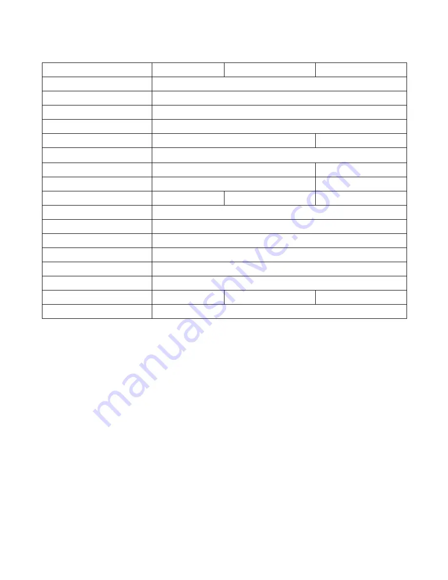
background image

8

Omni 1x5

Omni 1x10

Omni 2x5

Power input connector

Neutrik 

powerCON

 20A NAC3MPA-1

Power loop-thru connector

Neutrik 

powerCON

 20A NAC3MPB-1

Input power

85-250 VAC @ 47-66Hz

Max loop-thru power

10A @ 250 VAC

Power consumption

15W

30W

Input fuse

MAX 1A 250V  (

3AB 1/4”x1-1/4” style)

Number of DMX inputs

1

2

Number of DMX loop-outs

1

2

Number of isolated outputs

5

10

10

DMX input connector(s)

Neutrik 5 pin male XLR NC5MAH (3 pin XLR also available)

DMX output connectors

Neutrik 5 pin female XLR NC5FAH (3 pin XLR also available)

Galvanic power isolation

500VAC (1000VDC) per output circuit

Optical data isolation

5000VAC per output circuit

Voltage suppression

5.8V @ 57A (330W)

Dimensions

1 rack space chassis – 19”x5”x1.75”

Weight

4lb 4oz

4lb 6oz

4lb 8oz

Power cable provided

3' 18 awg NEMA5-15 (Edison) to Neutrik NAC3FCA 

powerCON


XLR connectors

5 pin signal list:

1. Signal Common – cable shield (not chassis ground) *connected to isolated 

ground of 5VDC power for each outlet (i.e. each signal common is independent)

2. Data -  or “B”
3. Data + or “A”

4.

Data - (for 2

nd

 data line or other manufacturer specific use)

5.

Data + (for 2

nd

 data line or other manufacturer specific use)

* In the Omni DMX splitter pins 4 & 5 are connected between the data input and loop-
out connectors.  This pin to pin connection is not modified by the splitter in any way.  
Pins 4 & 5 on the isolated outputs are not used or connected in any way.

Omni DMX Splitter V1.01 1/31/19

Summary of Contents for Omni 1x10

Page 1: ...1 Omni DMX Splitter User Manual Omni 1x5 1x10 2x5 Applied Electronics 722 Bluecrab Rd Newport News VA 23606 800 883 0008 appliednn com Omni DMX Splitter V1 01 1 31 19 ...

Page 2: ...lines in excess of 1000ft are not recommended Interference Outside electromagnetic sources can corrupt the data on a DMX line and cause undesired operation of lighting fixtures Surges Voltage spikes from shorted cables and faulty fixtures can feed down the data chain and damage other fixtures or the console The Omni splitter helps eliminate all of these issues by Isolation Each output transmits it...

Page 3: ...he NAC3FCB cable mount plug The loop thru connection is limited to 10A Do not connect more than 10A of load current to this outlet as it may cause damage to the unit Each splitter comes with a 3 powerCON to NEMA 5 15 Edison input power cable 1 powerCON A B jumper cables may be purchased separately to interconnect multiple units Data input XLR input and loop out data connectors are provided for fee...

Page 4: ...nated Data output XLR output data connectors are provided for feeding DMX to up to 32 receivers each The power supply for each output is galvanically isolated from the input and the other outputs The data line of each output are optically isolated from the input and the other outputs Maintenance No routine maintenance procedures are required as your Omni DMX splitter is a solid state device that s...

Page 5: ...LED No power supplied to unit Check the source power outlet and the power supply cable Confirm that the powerCON connector is twisted into the locked position Input power fuse blown Remove fuse turn and check If blown replace with MAX 1A 250V fuse No signal LED and no DMX from loop out port No data being received from transmitter console Test data line with device No signal LED but good DMX confir...

Page 6: ...that the dimple signifying the pin 1 end of the chip is at the same end as the notch in the socket right hand end as pictured 6 Gently press the spare chip until it seats fully in the socket being careful not to bend any leads 7 Replace the top cover 8 Re test the unit for correct operation If after following the trouble shooting guide you believe it necessary to replace the output RS 485 and or o...

Page 7: ...re chip until it seats fully in the socket being careful not to bend any leads 7 Replace the top cover 8 Re test the unit for correct operation Technical Details Omni DMX Splitter V1 01 1 31 19 System Block Diagram Output PCB ...

Page 8: ... 5000VAC per output circuit Voltage suppression 5 8V 57A 330W Dimensions 1 rack space chassis 19 x5 x1 75 Weight 4lb 4oz 4lb 6oz 4lb 8oz Power cable provided 3 18 awg NEMA5 15 Edison to Neutrik NAC3FCA powerCON XLR connectors 5 pin signal list 1 Signal Common cable shield not chassis ground connected to isolated ground of 5VDC power for each outlet i e each signal common is independent 2 Data or B...

Page 9: ...s the right to inspect product for damage not covered under this guarantee before conducting repairs The customer is responsible for shipping product to Applied for service If repaired under warranty product return shipping will be paid by Applied Items repaired or replaced under warranty do not extend or renew the original guarantee period Except as expressly stated and warranted herein i Applied...

Reviews: