background image

APPENDIX


GP-3460 POS Terminal


17


Chapter 5 TROUBLESHOOTING 

This chapter provides suggestions on how to locate and solve problems that may 
arise while using your GP-3460. If you cannot solve a problem with the following 
information, contact your dealer for further assistance. 
 

With the power on, there is no image or abnormal display on the 
terminal screen. 

A. Make sure the power cord is firmly connected.  

(Ensure the AC voltage range should be between 100V~240V.) 

B. Confirm the function of the power adapter by testing another one.  


U

ATTENTION 

If step A, B do not help and the problem remains unsolved, contact your dealer 
for further assistance.


The Touch Panel is not working properly. 

1.


Check whether the Touch Panel Driver has been correctly installed in the PC. 

2.


If the touch panel can detect the finger touch but the cursor is drifting, use 
the touch tool (from the Driver CD) to execute calibration or draw test.  

 
The Integrated VFD/LCD display is not working properly. 

1.


Make sure the power switch under the display panel is turned on. 

2.


Make sure the contrast setting is properly adjusted. 

3.


Make sure the RJ45 connector is firmly connected to the COM2 (RJ45) 
port at the bottom side of the monitor and the jumper is set to


DC 5V. 

See page 24 for the jumper setting. 


The Magnetic Stripe Reader is not working properly. 

1.


Check whether the MSR is powered properly by the system: if the buzzer  
beeps twice after restarting the system, it means the MSR is powered 
correctly. 

2.


Test the reader with another card. If that works, the MSR is functioning  
properly.  

3.


Wipe the MSR slot with a soft cloth then try again.  


NOTE:  

If the problem goes beyond the scope of this manual or remains unresolved, DO 
NOT repair it by yourself, contact your dealer for assistance. 

All manuals and user guides at all-guides.com

all-guides.com

Summary of Contents for Grand POS GP-3460

Page 1: ...http www appostar com Grand POS GP 3460 User s Manual Edition JAN 2014 Version 1 00 All manuals and user guides at all guides com a l l g u i d e s c o m...

Page 2: ...eir w recycling ut where city office product s Comm d found to of the FCC ainst har rates uses sed in acc dio comm ot occur rference to equipment one or m ceiving an etween the to an outl ected xperie...

Page 3: ...ublication from time to time in the contents hereof without obligation of the manufacturer to notify any person of such revision or changes Copyright This work is copyrighted Reproduction or retransmi...

Page 4: ...roken The following instructions will help you to make better use of this product 1 Keep the machine away from locations subject to high humidity dust or temperatures that exceed the specification Ref...

Page 5: ...READER MSR INSTALLATION 8 2 2 CPD 3210 VFD LCD CUSTOMER DISPLAY INSTALLATION 9 2 3 PCM SERIES 2SECOND LCD INSTALLATION 10 CHAPTER 3 SOFTWARE INSTALLATION 11 3 1 MAINBOARD DRIVER INSTALLATION 11 3 2 PE...

Page 6: ...and solid color opti eration en wing items act the de it 2 e User T OVER One POS the trend low noi POS is sk d stand ons for t nvironmen s are con ealer from Power A 5 Drive r s Manua RVIEW Terminal...

Page 7: ...POS Terminal 3 1 2 Appearance Front View Rear View 15 LCD touch panel Front bezel Base MSR module optional Attachable on both sides I O Cover Hinge cover Storage for power adaptor All manuals and user...

Page 8: ...PRODUCT OVERVIEW 4 GP 3460 POS Terminal Side View Tilt angle 0 85 degree 85 All manuals and user guides at all guides com...

Page 9: ...x 4 t with RJ45 onfusion w Remove e HDD S slot n No x 2 FF splay 4 5 with the L the lid be SSD brack o Por COM COM COM Stora COM CAS DRAW LAN port efore use ket the H P rt M 1 Ser M 2 Ser M 4 Ser age...

Page 10: ...le dual VGA Port 1 x VGA DB15 Speaker 2 x Integrated 1 5W stereo speaker Ethernet Port 1 x RJ45 10M 100M 1GB Base T Parallel Port 1 x Bi directional Parallel USB Port 4 x USB 2 0 Type A DC output Jack...

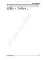
Page 11: ...GP 3460 POS Terminal 7 Mechanical Housing Color Black Construction ABS SECC Dimension W x D x H 350 x 242 x 320 mm NET GROSS N W 5 8 kg G W 7 7kg All manuals and user guides at all guides com a l l g...

Page 12: ...to prevent possible damage to the product 2 1 Magnetic Stripe Reader MSR Installation An optional MSR can be installed in both right left side of GP 3460 By default the MSR is installed on the right s...

Page 13: ...Step1 Use flat screw driver to remove the stand cover and break up the lid at the bottom of the cover Step2 Fit in the bracket and screw it up Step3 Install the VFD onto the bracket and lead the cabl...

Page 14: ...the stand cover and break up the lip at the bottom of the cover Step2 Fit the bracket in position with 2 screws Step3 Reinstall the stand cover Step4 Hang the LCD onto the bracket and REMEMBER to scr...

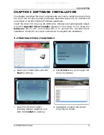
Page 15: ...t and the Appostar Driver Installer appears on the screen If not locate the Setup exe file at CD and double click it to execute the one step driver installation Follow the on screen instructions to co...

Page 16: ...f Select Install this driver software anyway in Windows Security window to continue the installation procedure g Select Install in Windows Security window to continue the installation procedure h Sel...

Page 17: ...ipheral Devices b Click Touch Panel c Click Next on the Welcome screen to continue d Ignore the Install PS 2 interface driver option Click Next to continue e Select the Install RS232 interface driver...

Page 18: ...k Next to continue h Select the Destination Folder or use the default one listed i Type a Folder name or use the default one listed Click Next to continue j A progress window appears Please wait k Cli...

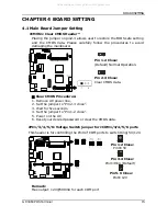
Page 19: ...Clear CMOS data Clear CMOS Procedures 1 Remove AC power line 2 Set the jumper to Pin 2 3 close 3 Wait for five seconds 4 Set the jumper to Pin 1 2 close 5 Power on the AC 6 Reset your desired passwor...

Page 20: ...4 Close Pin1 Ring 6 5 Pin 5 6 Close Pin1 12V Remark Max output 12V 500mA for each COM port JCOM2 Serial Port Connector Pin Assignment 1 COM2_RI 2 COM2C_DSR 3 COM2C_TXD 4 COM2C_RXD 5 COM2C_RTS 6 COM2C_...

Page 21: ...h but the cursor is drifting use the touch tool from the Driver CD to execute calibration or draw test The Integrated VFD LCD display is not working properly 1 Make sure the power switch under the dis...

Reviews: