KP-5600 Se
Step 3 Fi
u
o
Step 4 C
(F
ATTENT
If the cu
Trouble
eries Touch
ix the cus
nit with 2
n the I/O
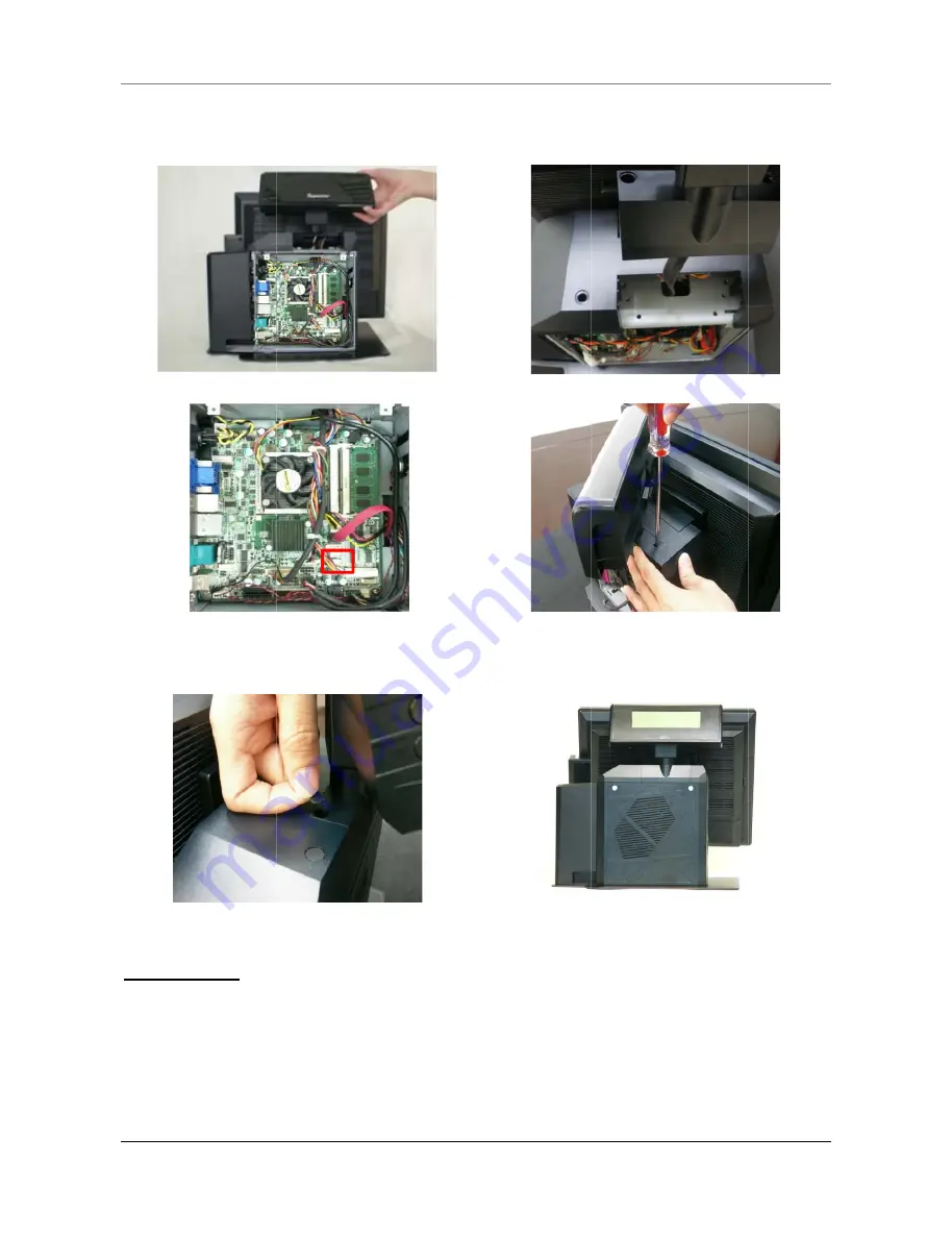
Fig
Fig
Cover the
Figure 2-h
Fig
TION
stomer d
eshooting
h POS Term
stomer dis
screws. P
O board as
gure 2-d
gure 2-f
screw ho
h, 2-i)
gure 2-h
isplay do
g.
minal
splay into
Plug the w
s shown i
oles with p
esn’t wor
o the brac
wafer con
n the pict
plastic lid
rk proper
ket and t
nector to
ture. (Fig
ds and rei
ly, please
HARDWA
hen fix th
the COM
ure 2-f)
Figure 2
Figure 2
nstall the
Figure
e refer to
RAE INST
hem onto
6 port wi
2-e
2-g
e rear cov
2-i
CH.5
TALLATION
11
the main
th DC 5V
ver.
N
All manuals and user guides at all-guides.com


