background image


16

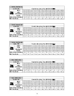
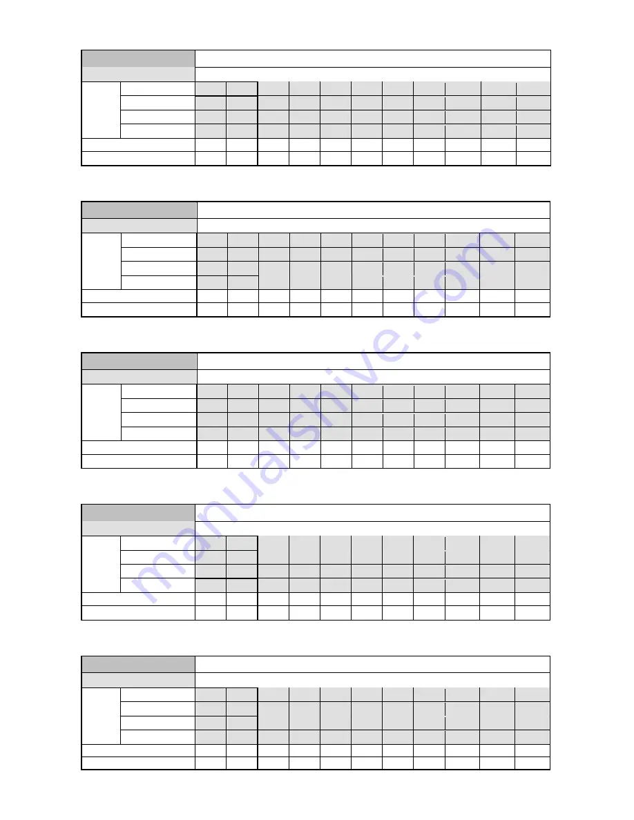
   NTSC (MUX ON) 


Audio OFF 

Possible Recording Time HDD=20GB ( 

hour 

BEST 

3.7 

4.5 

6.7 

11.3

24.8

56.5

110.7

192.1 

544.7 

816 

1087.3

HIGH 

4.5 

5.6 

8.4 

14.1

31.0

70.6

138.4

240.1 

680.9 

1020

1359.1

STANDARD 

5.6 

7.5 

11.3

18.8

41.4

94.1

184.6

320.2 

907.9 

1360

1812.2

Image 

Quality 

BASIC 

7.5 

11.3 

16.9

28.2

62.1

141.2

276.9

480.3  1361.9  2040.1

2718.3

Refresh Rate (Field/Sec) 

60 30 20 12 5.5 2.4 

1.22

0.71

1/4  1/6  1/8 

REC Time Mode 

2 hr 

4 hr 

6 hr 

12 hr

24 hr

48 hr

96 hr

168 hr 

480 hr 

720 hr

960 hr


   NTSC (MUX OFF) 


Audio ON 

Possible Recording Time HDD=20GB ( 

hour 

BEST 

3.7 

4.5 

8.9 

13.2

26 

54 

96.8

151

547 

818.3

1089.5

HIGH 

4.5 

5.6 

11.1

16.5

32.2

66.2

116.9

178.9 

683.8  1022.8

1361.9

STANDARD 

5.6 

7.5 

14.7

21.8

42.3

85.5

147.4

219.2 

911.7  1363.8

1815.9

Image 

Quality 

BASIC 

7.5 

11.3 

21.8

32.5

61.6

120.7

199.4

283.1  1367.6  2045.7

2723.9

Refresh Rate (Field/Sec) 

60 

30 

**20

**12

**5.5

2.4 

1.22

0.71 

 1/4 

 1/6 

 1/8 

REC Time Mode 

2 hr 

4 hr 

6 hr

12 hr

24 hr

48 hr

96 hr

168 hr 

480 hr 

720 hr

960 hr


   NTSC (MUX OFF) 


Audio OFF 

Possible Recording Time HDD=20GB ( 

hour 

BEST 

3.7 

4.5 

13.5

27.1

58.7

113

194.4 

547 

818.3

1089.5

HIGH 

4.5 

5.6 

11.3

16.9

33.9

73.4

141.2

243

683.8  1022.8

1361.9

STANDARD 

5.6 

7.5 

15 

22.6

45.2

97.9

188.3

324

911.7  1363.8

1815.9

Image 

Quality 

BASIC 

7.5 

11.3 

22.6

33.9

67.8

146.9

282.5

486

1367.6  2045.7

2723.9

Refresh Rate (Field/Sec) 

60 

30 

**20

**12

**5.5

2.4 

1.22

0.71 

 1/4 

 1/6 

 1/8 

REC Time Mode 

2 hr 

4 hr 

6 hr

12 hr

24 hr

48 hr

96 hr

168 hr 

480 hr 

720 hr

960 hr


   PAL (MUX ON) 


Audio ON 

Possible Recording Time HDD=20GB ( 

hour 

BEST 

3.8 

4.5 

6.7 

11.1

19.7

36.3

67.2

108.2 

454.3 

680.4

906.4

HIGH 

4.5 

5.7 

8.4 

13.9

24.7

45.2

82.7

131.2 

573.9 

859.4

1145

STANDARD 

5.7 

7.7 

11.4

18.8

33.1

60 

107.5

166.6 

778.9  1166.4

1553.9

Image 

Quality 

BASIC 

7.7 

11.4 

16.7

27.4

47.7

84.9

147.4

219.9  1147.8  1718.9

2290

Refresh Rate (Field/Sec) 

50 25 17 10 5.5 2.9 

1.52

0.88

1/4  1/6  1/8 

REC Time Mode 

3 hr 

6 hr 

9 hr 

12 hr

24 hr

48 hr

96 hr

168 hr 

480 hr 

720 hr

960 hr


   PAL (MUX ON) 


Audio OFF 

Possible Recording Time HDD=20GB ( 

hour 

BEST 

3.8 

4.5 

6.7 

11.3

20.3

38.4

74.5

128.8 

454.3 

680.4

906.4

HIGH 

4.5 

5.7 

8.5 

14.2

25.6

48.5

94.2

162.7 

573.9 

859.4

1145

STANDARD 

5.7 

7.7 

11.6

19.3

34.8

65.8

127.8

220.8 

778.9  1166.4

1553.9

Image 

Quality 

BASIC 

7.7 

11.4 

17.1

28.5

51.3

97 

188.4

325.5  1147.8  1718.9

2290

Refresh Rate (Field/Sec) 

50 25 17 10 5.5 2.9 

1.52

0.88

1/4  1/6  1/8 

REC Time Mode 

3 hr 

6 hr 

9 hr 

12 hr

24 hr

48 hr

96 hr

168 hr 

480 hr 

720 hr

960 hr

Summary of Contents for DVR-3011S

Page 1: ...Before trying to connect or operate this product please read this manual completely INSTALLATION OPERATION MANUAL Digital Video Recorder DVR 3011S ...

Page 2: ......

Page 3: ...r model of DVR for you will lose the data you have stored in the hard disk s if you do so You are free to use the same hard disks between DVRs belonging to a single model Danger of explosion if the Lithium battery RTC Battery is incorrectly replaced Danger of explosion if battery is incorrectly replaced Replace only with the same or equivalent type recommended by the manufacturer Dispose of used b...

Page 4: ... 3 2 Hard Disk Drive Installation 12 3 3 System Information 12 3 4 Updating System Software 14 4 BASIC OPERATIONS 15 4 1 Configuring Recording Settings 15 4 2 Recording Operations 18 4 3 Playback Operations 23 4 4 Search Operations 25 4 5 Backup Operations 29 4 6 Key Lock Operation 32 5 MENU SETUP 33 5 1 REC SETTING 34 5 2 ALARM MOTION SETTING 35 5 3 CLOCK TIMER 38 5 4 COMMUNICATION 39 5 5 DISK SE...

Page 5: ... 1 Setup 43 6 2 Communication Protocol 43 7 IDE HARD DISK INSTALLATION 46 7 1 Built in hard disk 46 7 2 Mobile Rack 47 8 SYSTEM DEFAULT 50 9 O S D MESSAGE 52 10 INDEX TABLE 53 11 SPECIFICATIONS 54 12 COMPATIBLE MULTIPLEXER DRIVES 55 ...

Page 6: ...1 2 Product Features Stores video in hard disk drives instead of VCR tapes Maximum 2 hard disk drive capability One removable Hard disk drive hot swapping capability Pre alarm image recording Capable of working with various known multiplexers Time lapse and real time recording Refresh rate up to 60 IPS 50 IPS for PAL Image quality selectable at 4 different levels for recording Event Timer Alarm re...

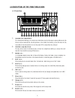
Page 7: ... the device PAUSE button In a playback display press this to freeze the display During the freeze press to display one frame field of a picture at a time in the forward direction Illuminate green in PAUSE mode PLAY button Press to play back a recorded video from the hard disk Illuminate green in PLAY mode STOP button Press to stop playing back a recorded video or recording video into a hard disk I...

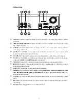
Page 8: ...lights up to indicate the alarm record setting is on DISK Indicator The indicator shows the operation status of the unit s hard disk drives The green light indicates the hard disk drive is storing or retrieving data The red light signals the hard disk drive is filling up The orange light indicates the hard disk is retrieving at disk full status Shuttle Ring The shuttle can be moved forward and bac...

Page 9: ...sing critical images RS 232 Port The RS 232 communication port functions as a connector to an external control device Please refer to RS 232 RS 485 Protocol for more details VIDEO OUT Connector The connector provides the unit s composite video signals to a MUX MONITOR Connector The connector provides the unit s composite video or a MUX s live signal if connected to a display device AUDIO OUT This ...

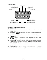
Page 10: ... such as buzzers or lights 5V 0V Active 4 ALARM RESET INPUT This pin connects to an alarm clear device for clearing an alarm 5V 0V Active 5 RECORD IN INPUT This pin connects to a record trigger device for starting a record 5V 0V Active 6 SWITCH OUT OUTPUT This pin sending out timing signals falling negative to a multiplexer connects to a multiplexer s trigger terminal so the multiplexer can switch...

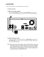
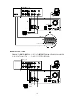
Page 11: ...NET 10 100 CONNECTING WITH A MULTIPLEXER To match the multiplexer s recording speed please set the MULTIPLEXER option to ON on the REC SETTING page in the setup menu when it is connected with a multiplexer Please refer to section 5 1 MULTIPLEXER option Caution When being set up so that an multiplexer may record only the Alarm in camera during alarm record or when there is only one camera input if ...

Page 12: ...T 10 100 Monitor Video in Audio in CONNECTING WITH A QUAD Please set the MULTIPLEXER option to OFF on the REC SETTING page in the setup menu when it is connected with a quad Please refer to section 5 1 MULTIPLEXER option SD Card RS 232 ALARM DC12V AUDIO IN IN OUT OUT VIDEO TO MONITOR TO MUX S VCR IN FROM MUX MAIN MONITOR I O Audio IN OUT S video Quad Monitor Video in Audio in PC RS 485 ETHERNET 10...

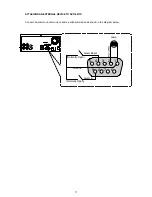
Page 13: ... out alarm input and a peripheral device as shown in the diagram below SD Card RS 232 ALARM DC12V AUDIO IN IN OUT OUT VIDEO TO MONITOR TO MUX S VCR IN FROM MUX MAIN MONITOR I O 1 2 3 4 5 6 7 8 9 Alarm Reset Normally Open Normally Open Alarm in Ground RS 485 Lamp ...

Page 14: ... RPM ST380013A 80G 7200 RPM ST3120026A 120G 7200 RPM ST3160023A 160G 7200 RPM ST3200822A 200G 7200 RPM ST3250823A 250G 7200 RPM Seagate ST3400832A 400G 7200 RPM 4A160J0 1A 160G 5400 RPM 4R080L0 1 80G 5400 RPM 5A300J0 1A 300G 5400 RPM 6Y080L0 80G 7200 RPM 6Y080L0 3 80G 7200 RPM 6Y120L0 1 120G 7200 RPM 6Y200P0 1A 200G 7200 RPM 6Y250P0 1A 250G 7200 RPM 6B300R0 300G 7200 RPM 6L080P0 RoHS 80G 7200 RPM ...

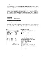
Page 15: ...Time Press the Display button once the DVR will display the following sample message plus the default display Press the Display button again the unit will not display any OSD message Press the button one more time to back to the default display Table 3 3 A Description of Table 3 3 A 1 2 59G Total capacity of installed hard disk 59 GB 12 4 HR Total 12 4 hour recording time available Timer record ac...

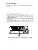
Page 16: ...g the system software which will take approximately 90 seconds to process 5 Restart the unit when the device sounds a tone twice and displays the message PLEASE RESTART The process is complete If you have already followed the procedure 1 5 the unit however not being able to power on Please first check if the SD card you are using is functioning and the file is intact And then start procedures 1 5 ...

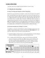
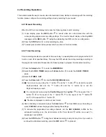
Page 17: ...cted If a multiplexer is connected for optimum image recording and playback the record speed of the multiplexer must be correctly adjusted to match the DVR and set the MULTIPLEXER option on the setup menu to ON This can be done by either of methods detailed below 1 If an APPRO multiplexer is connected for use you can program the REC time mode of the multiplexer by referring to the table below each...

Page 18: ... 6 11 3 16 9 33 9 73 4 141 2 243 683 8 1022 8 1361 9 STANDARD 5 6 7 5 15 22 6 45 2 97 9 188 3 324 911 7 1363 8 1815 9 Image Quality BASIC 7 5 11 3 22 6 33 9 67 8 146 9 282 5 486 1367 6 2045 7 2723 9 Refresh Rate Field Sec 60 30 20 12 5 5 2 4 1 22 0 71 1 4 1 6 1 8 REC Time Mode 2 hr 4 hr 6 hr 12 hr 24 hr 48 hr 96 hr 168 hr 480 hr 720 hr 960 hr PAL MUX ON Audio ON Possible Recording Time HDD 20GB ho...

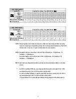
Page 19: ...ate Field Sec 50 25 17 10 5 5 2 9 1 52 0 88 1 4 1 6 1 8 REC Time Mode 3 hr 6 hr 9 hr 12 hr 24 hr 48 hr 96 hr 168 hr 480 hr 720 hr 960 hr NOTE Recording times on the tables above are estimated For actual available recording time of a recording configuration please refer to the system information of the DVR Please refer to section 3 3 system information for more details NOTE No audio function at the...

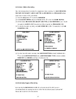
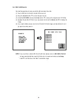
Page 20: ...ake the following steps to program the scheduled recording 1 Press the Setup button to enter the MAIN MENU 2 Select the CLOCK TIMER and press the Enter button to enter the CLOCK TIMER page 3 Select the TIMER SET 4 Press the Enter button to enter the REC SCHEDULE table 5 You can set up by using the button and the button to locate the specific day hour minute and use the button and the v button to s...

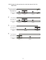
Page 21: ... from menu to start recording NOTE If you activate the recording function before the scheduled recording the unit will operate recording as shown in the diagram below and keep those Images in different files 03 00 06 00 08 00 12 00 14 00 START END START END Start Manual Recording Timer Manual Timer Manual NOTE LIVE images may be freezed But it isn t a failure ...

Page 22: ...END START END S 00 00 00 00 00 00 00 00 M 00 00 00 00 00 00 00 00 T 00 00 00 00 00 00 00 00 W 00 00 00 00 00 00 00 00 T 00 00 00 00 00 00 00 00 F 00 00 00 00 00 00 00 00 S 00 00 00 00 00 00 00 00 OK CANCEL TO MOVE TO CHANGE MAIN MENU RECORD ALARM MOTION CLOCK TIMER COMMUNICATION DISK SYSTEM GOTO CLOCK TIMER PAGE CLOCK TIMER CLOCK SET REC ENABLE OFF TIMER SET MAIN PAGE TIMER REC ENABLE ...

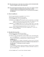
Page 23: ...the Enter button to enter the MOTION SETTING PAGE set MOTION ENABLE TO ON and set a suitable SENSITIVITY and REGION according to the video sources 4 2 4 Externally triggered Recording By connecting the RECORD IN of ALARM I O on the rear panel of the DVR you can activate deactivate the recording function of a DVR The file will be kept with a prefixed R Please refer to section 2 3 for more details M...

Page 24: ...al or Externally Triggered Recording Alarm Takes Place Actual Recording Speed Normal Alarm Normal Timer Recording Actual Recording Speed Alarm Takes Place Timer Recording Actual Recording Speed Alarm Takes Place Timer Recording Actual Recording Speed Alarm Takes Place Normal Alarm Normal Normal Alarm Alarm Normal ...

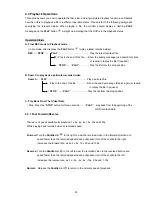
Page 25: ...Play a selected file Play to the end of the file Show the ending message Search again or rewind to replay the file if required STOP PLAY Play the file from the stop position C Play Back From The Oldest Data Stop Press the STOP button for three seconds PLAY play back from the beginning of the HDD recorded data 4 3 1 Fast Forward Reverse There are 7 speeds available for playback 1x 2x 4x 8x 16x 30x ...

Page 26: ...e recorded speed Each subsequent turn of the shuttle to the left increases the reverse rate as 1 2 1 4 1 8 and 1 16 4 Normal Release the Shuttle dial and then press the PLAY button to return to the normal speed of playback 4 3 3 Play Back Picture by picture While playing back recorded video at the recorded speed 1 Press the PAUSE button for the picture by picture mode 2 There are two ways by PAUSE...

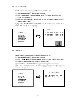
Page 27: ...ction 1 Press the Search button to enter the search mode 2 Select the FULL LIST and press the Enter button to access the complete list of recorded video 3 Highlight the specific recorded video of your requirement and press the Enter button to display the selected video Key Operation Press the and v buttons to select a video press the and buttons to flip over a page NOTE T Timer recording R Externa...

Page 28: ...following steps to proceed with the time list search function 1 Press the Search button to enter the search mode 2 Select the TIME SEARCH and press the Enter button to access the time setting page 3 Set the time period you wish to search for the recorded video 4 Press the Enter button to start searching and displaying the concerned image 5 If no video is found please return to the time setting pag...

Page 29: ...also set up by using the Shuttle Ring and the Jog Dial to move eye focus is the equal of the button is the equal of the button is the equal of the button and is the equal of the v button 5 There are 5 levels of recording range modes to choose from 1 Hour 10 Minutes 1 Minute 10 Seconds and 1 Second Select the specific field of your requirement and press the Enter button to enter the next level If y...

Page 30: ...irement and press the Enter button to display the image 5 If you need another please return to the SD card JPG file list page and repeat steps 3 and 4 again for another search NOTE If you would like to delete JPG file in the SD card please return to SD CARD JPG FILE list page and highlight the specific JPG file of your requirement and press the Setup button and then select the Yes to delete the im...

Page 31: ...om HD1 to HD2 Stay on the DISK SETTING page Use the and v buttons and to highlight BACKUP select FULL then press the Enter button to proceed ALARM Duplicate all the alarm event recorded video from HD 1 to HD2 Stay on the DISK SETTING page Use the and v buttons and to highlight BACKUP select ALARM then press the Enter button to proceed MAIN MENU RECORD ALARM MOTION CLOCK TIMER COMMUNICATION DISK SY...

Page 32: ...cted video a warning message HD2 SPACE NOT ENOUGH will be displayed on the screen Please insert a larger capacity of hard disk drive and start the process all over again MAIN MENU RECORD ALARM MOTION CLOCK TIMER COMMUNICATION DISK SYSTEM GOTO DISK PAGE DISK SETTING REFORMAT HD2 USAGE BACKUP FULL SD FILE ALARM SELECT MAIN PAGE BACKUP ALARM TO HD2 MAIN MENU RECORD ALARM MOTION CLOCK TIMER COMMUNICAT...

Page 33: ...he SD Card The quantity of pictures that can be stored depends on the SD card capacity It depends on SD card capacity how many pictures can be stored You can have the saved images printed out in any computer The image is stored in the JPEG compressed format If more than one clip is stored in a SD card file names will be assigned in sequence as shown below SAVE TO J0000 JPG SAVE TO J0001 JPG SAVE T...

Page 34: ...ion protects the unit against unauthorized use by disabling the entire front panel controls Simultaneously press these two and buttons as shown below for at least 3 seconds to lock the unit to release the Key Lock simultaneously press these two buttons again Power Display Enter Monitor Setup PLAY STOP REC FWD REV PAUSE A rec Search T rec POWER DISK 11 14 MAIN MENU RECORD ALARM MOTION CLOCK TIMER C...

Page 35: ...uttons within the menu setup mode are described in the paragraphs below KEY FUNCTIONS Setup button Press to enter the setup menu Press again to exit the setup mode v buttons and Press to select the desired item or entry for setting buttons and Press to highlight the desired option or to select the context for setting Enter button Press to enter the selected item and to save the setting Shuttle Rin...

Page 36: ...s 50 f s for a PAL unit recording rate can only function in a 352x240 352x288 for a PAL unit resolution REC QUALITY This option determines the image quality to be recorded The DVR stores images in the compressed format and allows the image quality to be altered by the image size There are 4 levels of image quality you can select from BEST HIGH STANDARD and BASIC Selecting the BEST image for use pr...

Page 37: ...arm recording when it detects an alarm input ON The device activates the alarm recording when it detects an alarm input OFF The device ignores the alarm signal when it detects an alarm input REC RATE This option is for the purpose of adjusting the number of pictures recorded every second into a storage disk when an alarm input is activated For a NTSC unit there are 5 different record speeds you ca...

Page 38: ...TYPE This option allows users to set a type of alarm input corresponding to the sensor signal in use NO Normally Open This is to be used with the type of alarm sensor whose contact remains open in normal conditions and closes in case of activation NC Normally Closed This is to be used with the type of alarm sensor whose contact remains closed in normal conditions and opens in case of activation AL...

Page 39: ...er the alarm recording just like the outside trigger signal Before using the motion detection function please turn the ENABLE option as ON and set the SENSITIVITY 1 5 to a suitable value NOTE The MOTION ENABLE option is not allowed set to ON when MULTIPLEXER option in REC SETTING page is set to ON it is because the motion detection function is for single camera only MOTION ENABLE This option enabl...

Page 40: ... scheduled recording TIMER This entry allows users to program the time each day that the DVR will start and stop recording There are two time periods each day available for scheduling The time is displayed in a 24 hour clock format If there is a time overlapping showing between two continual time period settings the device will automatically combine the two time period settings into one combined t...

Page 41: ...porting or exporting mode according to your applications ON Enables the RS 232 communication port When you wish the unit to be controlled by an external device please select this entry for use OFF Disables the RS 232 communication port RS 485 The RS 485 communication port can be either in an importing or exporting mode according to your applications ON Enables the RS 485 communication port When yo...

Page 42: ...k a recorded video from a HD2 this option must be set to REC For more details please refer to section 4 3 4 BACKUP This function allows you to duplicate data from HD 1 to HD 2 Please set HD 2 as BACKUP first For operation details please refer to section 4 5 1 FULL Duplicates all the recorded video from HD1 to HD2 ALARM Duplicates all the alarm event recorded video from HD 1 to HD2 SELECT Duplicate...

Page 43: ... Releases the key lock UPDATE Updates system software Note The log keeps an operation history on a revolving basis because of a limit in memory space When the log is full the newly registered record of an operation will replace the existing records from the oldest one OSD LANGUAGE This option allows you to select the OSD language display as English or Chinese 05 15 01 18 19 32 ON 05 15 01 18 19 32...

Page 44: ... the standard password 9999 SETUP PWD When this option is on user must pass the password check before entering the setup menu ON Enables it OFF Disables it DEFAULT This option allows you to reload the factory default setting Please do note that the password cannot be changed in the factory default setting SD SETUP The DVR 3011S offers a quick setup method by using a SD card If the user wants to se...

Page 45: ...n to ON in the COMMUNICATION page of the setup menu 6 1 3 Set the PC communication parameters 9600 bps No Parity 8 Data Bits 1 Stop Bit 6 2 Communication Protocol 6 2 0 General Command Format Lead Code 0x41 Dest ID Src ID Main category Second category Number of parameters Parameter 1 Parameter 2 End Code 0x4f Lead Code 0x41 Dest ID 0x01 Src ID 0x20 Main Category 0x01 Keys and Signals 0x02 Command ...

Page 46: ...GNAL_ALARM_RESET 165 SIGNAL_REC_OUT 169 SIGNAL_ALARM_IN 189 SIGNAL_ALARM_OUT 209 6 2 2 COMMAND Types 6 2 2 0 Command Main Category 0x02 6 2 2 1 Handshake Second Category 0x01 PC Request 0x41 0x01 0x20 0x02 0x01 0x00 0x4f DVR Response 0x41 0x20 0x01 0x02 0x08 0x00 0x4f 6 2 2 2 Request Time Second Category 0x02 PC Request 0x41 0x01 0x20 0x02 0x02 0x00 0x4f DVR Response 0x41 0x20 0x01 0x02 0x02 0x07 ...

Page 47: ...ter Slave Secondary Master Slave Every HDD use 12 Bytes 0 HDD Exist if 1 1 Active HDD if 1 2 Current HDD for REC if 1 3 Current HDD for PLAY if 1 4 7 Capacity 8 11 REC PLAY Position 6 2 2 7 Request REC Position Second Category 0x11 PC send 0x41 0x01 0x20 0x02 0x11 0x00 0x4f REC Mode DVR Response 0x41 0x20 0x01 0x02 0x11 0x08 HDD 0x0 4 Bytes REC Position 2 Bytes Image NO 0x4f Get HDD REC Position a...

Page 48: ...ng steps The jumper settings of hard disk drives for the system Location Jumper IDE 1 Compartment HD 1 Master IDE 2 Compartment HD 2 Master 7 1 Built in hard disk 1 1 Unscrew all the mounting screws on the mobile rack of the unit and detach it 2 3 2 Carefully lift the mobile rack to a vertical position 3 Unscrew the secured screws to detach the hard disk rack 4 5 4 Setting the jumper of your hard ...

Page 49: ...vice screwing in all the four screws 8 Attach the interface connector and the power connector to the drive Please note the red lining of the IDE cable and the red wire of power cable must line up side by side 10 Place the mobile rack back onto the device and screw it in 7 2 Mobile Rack 1 Make sure that the key unlocked 2 Pull the active handle outward to remove the carrier body away from the mobil...

Page 50: ... master position 5 Attach the interface connector and the power connector to the drive Please note the red lining of the IDE cable and the red wire of power cable must line up side by side 6 Place the HDD inside mobile rack Use four of the provided screws NOTE please make sure the steel connector see the arrow point is locked inside between rack and screw 7 Place the top cover back to the carrier ...

Page 51: ...49 8 Slide the carrier body back in the mobile rack 9 Push the carrier body further into the mobile rack until fully inserted 10 Push the active handle inward 11 Lock the Key ...

Page 52: ...MAIN MENU RECORD ALARM MOTION CLOCK TIMER COMMUNICATION DISK SYSTEM GOTO CLOCK TIMER PAGE CLOCK TIMER CLOCK SET REC ENABLE OFF TIMER SET MAIN PAGE TIMER REC ENABLE MAIN MENU RECORD ALARM MOTION CLOCK TIMER COMMUNICATION DISK SYSTEM GOTO ALARM MOTION PAGE ALARM MOTION ALM OPERATION OFF REC RATE 20F S REC QUALITY BEST AUDIO OFF ALM TYPE NO ALM DURATION 0 SEC PRE ALARM OFF MOTION SETTING MAIN PAGE AL...

Page 53: ...R COMMUNICATION DISK SYSTEM GOTO SYSTEM SETTING SYSTEM OPERATION LOG ENTER OSD LANGUAGE ENGLISH MENU BACKGND 2 BUZZER ON PASSWORD SET SETUP PWD OFF DEFAULT LOAD SD SETUP SAVE VERSION ENTER MAIN PAGE VIEW OPERATION LOG MAIN MENU RECORD ALARM MOTION CLOCK TIMER COMMUNICATION DISK SYSTEM GOTO DISK PAGE DISK SETTING REFORMAT HD 1 2 HD 2 USAGE REC BACKUP FULL SD FILE JPEG MAIN PAGE DISK REFORMAT CLEAR ...

Page 54: ...Y button or uses the SEARCH function but no video can be played 17 SET TO NTSC PLS RESTART System has to be set to NTSC please reboot PAL is similar 18 SOFTWARE UPDATE Software update 19 PLEASE RESTART The system should be rebooted after the software has been updated 20 NO DISK The user has pressed the Save key without putting in a SD card or there is a disk error 21 DATA NOT CONTINUOUS The system...

Page 55: ... oldest data will be kept in the index of the corresponding oldest data For any newly recorded data this approach will be applied until the disk becomes full HD1 HD1 1 12 02 02 12 20 55 1 12 02 02 12 20 55 2 12 02 02 13 30 33 2 01 30 03 16 00 34 3 01 30 03 16 00 34 2999 02 03 03 16 00 56 3000 LISTS 3000 02 03 03 16 00 56 3000 02 08 03 17 30 58 3000 LISTS In the rewrite recording mode when the arch...

Page 56: ...re Alarm Post Alarm Pre Alarm Recording 100 pictures Playback Speeds Frame Stepping 1 16x 1 8x 1 4x 1 2x 1x 2x 4x 8x 16x 30x 100x Record Search Alarm Time Event list Filter thumbnail SD card OSD Language English Chinese T Set up Menu Multi layer Log list 2000 records Alarm In Out 1 Alarm Input Output Built in Buzzer Yes Motion Detection Yes Communication Port RS 232 and RS 485 Software Upgrade Upg...

Page 57: ...16CH COLOR KOBI K 69C 4 NTSC PAL 4CH COLOR KOBI K 69C 9 NTSC PAL 9CH COLOR KOBI K 69C 16 NTSC PAL 16CH COLOR MultiView MV 14CD NTSC PAL 4CH COLOR MultiView MV 19CD NTSC PAL 9CH COLOR MultiView MV 116CD NTSC PAL 16CH COLOR PELCO Duplex 9CH PAL 9CH COLOR PELCO Duplex 16CH PAL 16CH COLOR PROVIDEO RMX 4CD NTSC 4CH COLOR PROVIDEO RMX 9CD NTSC 9CH COLOR PROVIDEO RMX 16CD NTSC 16CH COLOR ROBOT MV16e NTSC...

Reviews: