7
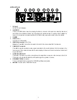
2.2 Rear Panel
6
7
8
9
5
3
4
2
1
1.
DC Input
DC12V/ 7A (AC Adapter).
2.
ALARM
I/O
This is a 10-PIN D-SUB connector including the Alarm In, Ground, 3-Pin Alarm Out, Disk Full, Record In,
Alarm Reset, and Reserved items for connecting with external devices. A quick-connect adapter for
Alarm I/O connections is included with the DVR. Refer to the next section, Alarm In/Out, for details.
3.
POWER
4.
VGA
interface:
Connect to a VGA monitor.
5.
VIDEO IN connectors
(Ch1~Ch4)
Video in:
These BNC connectors are used to connect to the video output from the cameras.
6.
VIDEO OUT connector
This BNC connector provides a video signal controlled by the control buttons in the front panel to the
main monitor. This connector transmits the video display in full-screen format, multi-screen format and
sequential format.
7.
AUDIO IN/ AUDIO OUT:
The audio in connector is used to connect the audio output from a camera or other devices to the DVR.
The audio out connector provides the unit’s audio signal to a speaker or stereo.
8.
ETHERNET
10/100
Connector
:
This is a standard RJ-45 connector for 10/100 Mbps Ethernet networks.
9.
MOUSE:
Connect with a “USB/ PS2” mouse.
Summary of Contents for DVR-3254S
Page 2: ......
Page 74: ...72 Figure 7 Verifying IP Address of DVR RMN0400372 V1 2 ...

